EasyManuals Logo

YASKAWA A1000 Series Installation Manual

YASKAWA A1000 Series
30 pages
To Next Page IconTo Next Page
To Previous Page IconTo Previous Page
Page #17 background imageLoading...
Page #17 background image
5 Installation Procedure
YASKAWA ELECTRIC TOBP C730600 38C 1000-Series Option AI-A3 Installation Manual 17
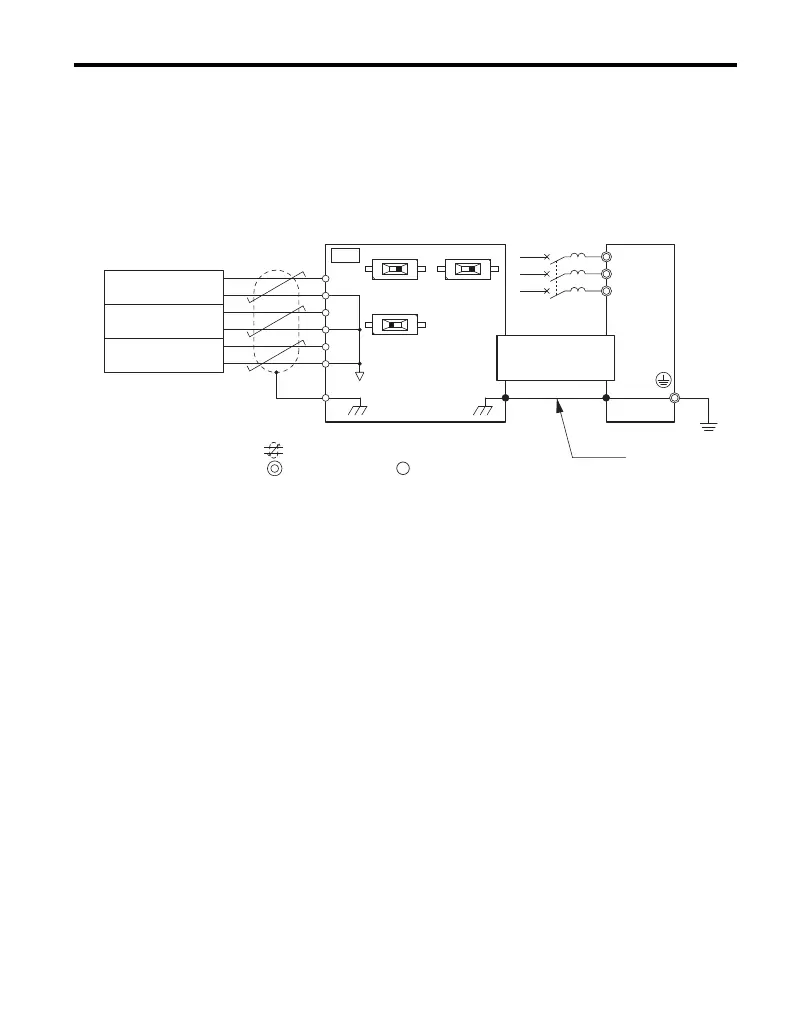
6. Wire the customer-supplied analog input signal to terminal block TB1 on the option.
Refer to Figure 9 for wiring instructions.
Connection Diagram
Refer to Table 4 on page 21 for a detailed description of the option board terminal
functions. To ensure accurate control, use a stable power supply for the voltage
reference source.
Figure 9
Figure 9 Option Connection Diagram
main circuit terminal, control circuit terminal
R/L1
T/L2
S/L3
V1
V
S1
S3
S2
I
VI
VI
AC
AC
AC
V2
V3
FE
TB1
Drive
AI-A3
Vout1
0 V
Vout2
0 V
Iout1
0 V
High precision voltage or
current reference generator
CN5
FE
twisted-pair shielded line
Voltage source
Voltage source
Current source
Ground wire
AI

Other manuals for YASKAWA A1000 Series

Questions and Answers:

Question and Answer IconNeed help?

Do you have a question about the YASKAWA A1000 Series and is the answer not in the manual?

YASKAWA A1000 Series Specifications

General IconGeneral
SeriesA1000
TypeAC Drive
AltitudeUp to 1000m without derating
Output Frequency0-400 Hz
Control MethodV/f Control
Overload Capacity150% for 60 seconds
Communication OptionsModbus, DeviceNet, Profibus, Ethernet/IP
Ambient Temperature-10 to 50°C
Storage Temperature-20 to 60°C
Humidity5% to 95% (non-condensing)
Enclosure RatingIP20
Horsepower0.5 to 1000 HP
Power Range0.4 - 630 kW (varies by voltage and model)
Protection FeaturesOvercurrent, Overvoltage, Undervoltage, Overheat
Cooling MethodFan Cooled
SafetySafe Torque Off (STO)

Related product manuals