5 Installation Procedure
16 YASKAWA ELECTRIC TOBP C730600 38C 1000-Series Option AI-A3 Installation Manual
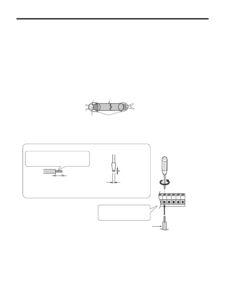
5. Prepare and connect the wire ends as shown in Figure 7 and Figure 8. Refer to
Wire Gauges and Tightening Torques on page 20 to confirm that the proper
tightening torque is applied to each terminal. Take particular precaution to ensure
that each wire is properly connected and wire insulation is not accidentally pinched
into electrical terminals.
WARNING! Fire Hazard. Tighten all terminal screws according to the specified tightening torque. Loose
electrical connections could result in death or serious injury by fire due to overheating electrical connections.
Tightening screws beyond the specified tightening torque may cause erroneous operation, damage the
terminal block, or cause a fire.
NOTICE: Heat shrink tubing or electrical tape may be required to ensure that cable shielding does not
contact other wiring. Insufficient insulation may cause a short circuit and damage the option or drive.
Figure 7
Figure 7 Preparing Ends of Shielded Cable
Figure 8
Figure 8 Preparing and Connecting Cable Wiring
Insulation
Shield
Shield sheath
Option terminal
Customer-supplied
analog input signal
FE
(Insulate with electrical tape
or shrink tubing)
Option terminal block
Preparing wire ends:
Screwdriver blade size
about 5.5 mm (7/32”)
When not using
crimped insulated
sleeves
Pull back the shielding and lightly
twist the end with fingers, keeping
the ends from fraying.
To customer circuit
(do not solder ends)
Loosen the screws and
insert the wire into the
opening on the terminal block.
Blade depth of
0.4 mm or less
Blade width of
2.5 mm or less

 Loading...


