3 Electrical Installation
16 YASKAWA ELECTRIC TOEP C710616 27D YASKAWA AC Drive - A1000 Quick Start Guide
Main Circuit Terminals
Note: Confirm the following when wiring models CIMR-A4A0930 and 4A1200:
" Remove the jumpers shorting terminals R/L1-R1/L11, S/L2-S1/L21, and T/L3-T1/L31 when operating with 12-phase
rectification. Refer to the Technical Manual for more information.
" When operating without 12-phase rectification, properly wire terminals R1/L11, S1/L21, and T1/L31 in addition to terminals
R1/L1, S1/L2, and T1/L3.
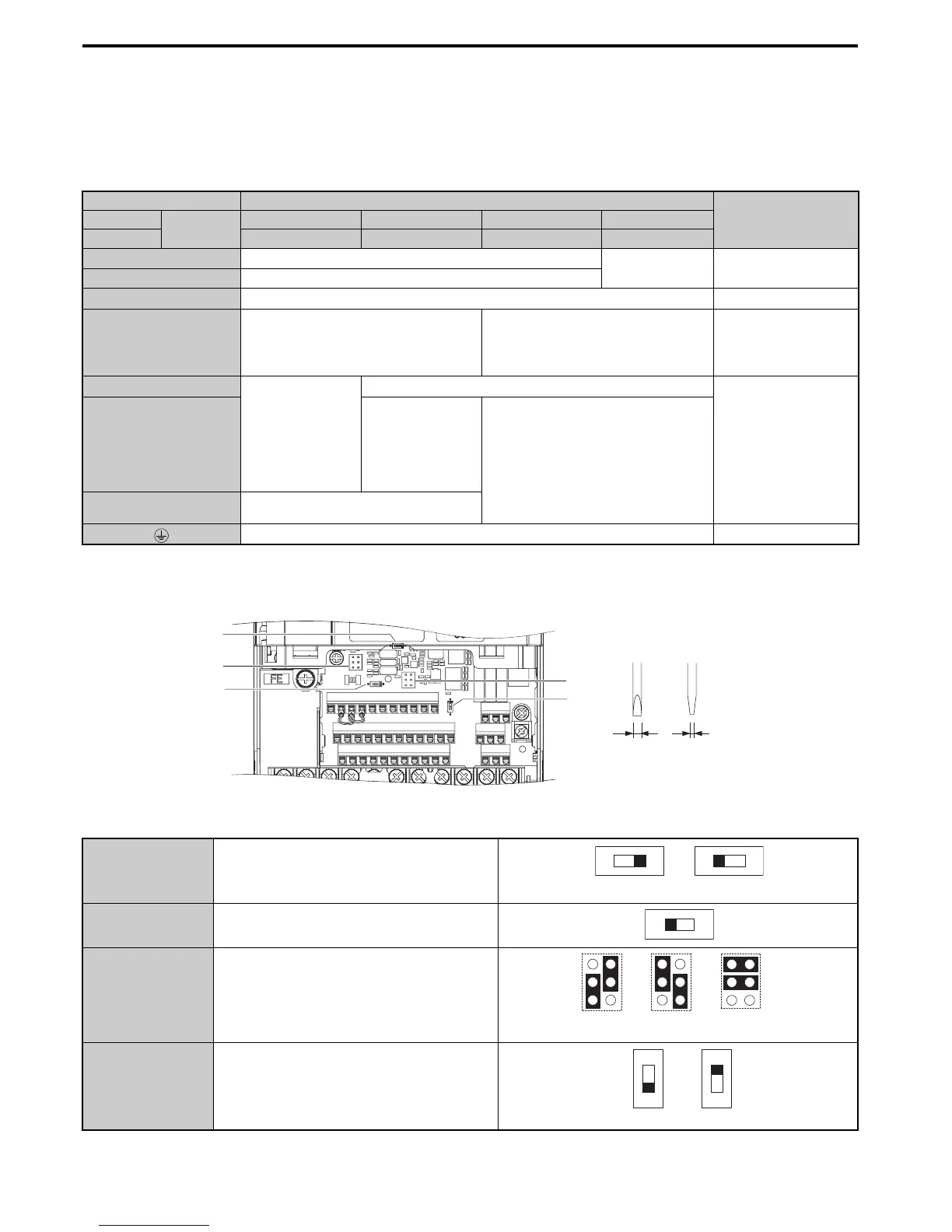
Control Circuit Terminals
The figure below shows the control circuit terminal arrangement. The drive is equipped with screwless terminals.
There are three DIP switches and two jumpers, S1 to S5, located on the terminal board.
Terminal Type
Function200 V Class
Model
CIMR-A
2A0004 to 2A0081 2A0110 to 2A0138 2A0169 to 2A0415 –
400 V Class 4A0002 to 4A0044 4A0058 to 4A0072 4A0088 to 4A0675 4A0930, 4A1200
R/L1, S/L2, T/L3
Main circuit power supply input
Main circuit power
supply input
Connects line power to
the drive
R1/L11, S1/L21, T1/L31 not available
U/T1, V/T2, W/T3
Drive output Connects to the motor
B1, B2
Braking resistor not available
Available for connecting
a braking resistor or a
braking resistor unit
option
+2
• DC reactor
connection (+1, +2)
(remove the
shorting bar
between +1 and +2)
• DC power supply
input (+1, −)
not available
For connection
• of the drive to a DC
power supply
(terminals +1 and – are
not CE or UL
approved)
• of braking options
• connection of a DC
reactor
+1, –
• DC power supply
input
(+1, −)
• DC power supply input (+1, −)
• Braking transistor connection (+3, −)
+3
not available
− Grounding terminal
S1 Terminal A2 Signal Selection
S2 RS422/485 Termination Resistor
S3
Safe Disable Input
Sink/Source/External Supply Selection
S4 Terminal A3 Analog/PTC Input Selection
E(G)
HC H1 H2 DM+ DM- IG R+ R- S+ S-
S1 S2 S3 S4 S5 S6 S7 S8 SN SC SP
V+ AC V- A1 A2 A3 FM AM AC MP RP AC
Use a straight-edge screwdriver
with a blade width of max 2.5 mm
and a thickness of max 0.6 mm to
release the terminals
S2
S3
S1
S4
S5
V
I
V
I
Current Voltage
Off
On
Source Sink
External 24 Vdc
Power Supply