26 YASKAWA ELECTRIC TOEP C710616 27D YASKAWA AC Drive - A1000 Quick Start Guide
6 Parameter Table
6 Parameter Table
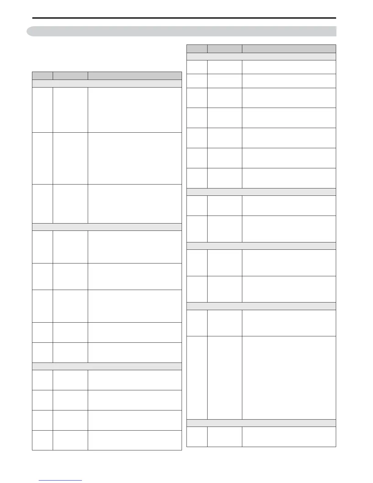
This parameter table shows the most important parameters.
Default settings are bold type. Refer to the Technical
Manual for a complete list of parameters.
No. Name Description
Initialization Parameters
A1-01
Access Level
Selection
0: View and set A1-01 and A1-04. U-
parameters can also be viewed.
1: User Parameters (access to a set of
parameters selected by the user, A2-01 to
A2-32)
2: Advanced Access (access to view and
set all parameters)
A1-02
Control
Method
Selection
0: V/f Control
1: V/f Control with PG
2: Open Loop Vector Control
3: Closed Loop Vector Control
5: Open Loop Vector Control for PM
6: Advanced Open Loop Vector Control for
PM
7: Closed Loop Vector Control for PM
A1-03
Initialize
Parameters
0: No initialization
1110: User Initialize (parameter values must
be stored using parameter o2-03)
2220: 2-wire initialization
3330: 3-wire initialization
5550: oPE04 error reset
Operation Mode Selection
b1-01
Frequency
Reference
Selection 1
0: Digital operator
1: Analog input terminals
2: MEMOBUS/Modbus communications
3: Option PCB
4: Pulse input (terminal RP)
b1-02
Run
Command
Selection 1
0: Digital operator
1: Digital input terminals
2: MEMOBUS/Modbus communications
3: Option PCB
b1-03
Stopping
Method
Selection
0: Ramp to stop
1: Coast to stop
2: DC Injection Braking to stop
3: Coast with timer
9: Simple Positioning Stop
b1-04
Reverse
Operation
Selection
0: Reverse enabled.
1: Reverse disabled.
b1-14
Phase Order
Selection
0: Standard
1: Switch phase order (reverses the direction
of the motor)
DC Injection Braking
b2-01
DC Injection
Braking Start
Frequency
Sets the frequency at which DC Injection
Braking starts when “Ramp to stop” (b1-03
= 0) is selected.
b2-02
DC Injection
Braking
Current
Sets the DC Injection Braking current as a
percentage of the drive rated current.
b2-03
DC Injection
Braking Time
at Start
Sets DC Injection Braking (Zero Speed
Control when in CLV/PM) time at start.
Disabled when set to 0.00 seconds.
b2-04
DC Injection
Braking Time
at Stop
Sets DC Injection Braking time at stop.
Acceleration/ Deceleration
C1-01
Acceleration
Time 1
Sets the time to accelerate from 0 to
maximum frequency.
C1-02
Deceleration
Time 1
Sets the time to decelerate from maximum
frequency to 0.
C1-03 to
C1-08
Acceleration/
Deceleration
Time 2 to 4
Set the accel/decel times 2 to 4 (set like C1-
01/02).
C2-01
S-Curve
Characteristic
at Accel Start
S-curve at acceleration start.
C2-02
S-Curve
Characteristic
at Accel End
S-curve at acceleration end.
C2-03
S-Curve
Characteristic
at Decel Start
S-curve at deceleration start.
C2-04
S-Curve
Characteristic
at Decel End
S-curve at deceleration end.
Slip Compensation
C3-01
Slip
Compensation
Gain
Sets the gain for the motor slip
compensation function used for motor 1.
C3-02
Slip
Compensation
Primary Delay
Time
Adjusts the slip compensation function
delay time used for motor 1.
Torque Compensation
C4-01
Torque
Compensation
Gain
Sets the gain for the automatic torque
(voltage) boost function and helps to
produce better starting torque. Used for
motor 1.
C4-02
Torque
Compensation
Primary Delay
Time
Sets the torque compensation filter time.
Carrier Frequency
C6-01
Drive Duty
Selection
0: Heavy Duty (HD) for constant torque
applications.
1: Normal Duty (ND) for variable torque
applications.
C6-02
Carrier
Frequency
Selection
1: 2.0 kHz
2: 5.0 kHz
3: 8.0 kHz
4: 10.0 kHz
5: 12.5 kHz
6: 15.0 kHz
7: Swing PWM1 (Audible sound 1)
8: Swing PWM2 (Audible sound 2)
9: Swing PWM3 (Audible sound 3)
A: Swing PWM4 (Audible sound 4)
B to E: No setting possible
F: User defined (determined by C6-03
through C6-05)
Frequency Reference
d1-01 to
d1-16
Frequency
Reference
1 to 16
Sets the frequency reference for the drive.
Setting units are determined by parameter
o1-03.
No. Name Description