6 Parameter Table
YASKAWA ELECTRIC TOEP C710616 27D YASKAWA AC Drive - A1000 Quick Start Guide 27
d1-17
Jog Frequency
Reference
Sets the Jog frequency reference. Setting
units are determined by parameter o1-03.
V/f Pattern for Motor 1
E1-01
Input Voltage
Setting
This parameter must be set to the power
supply voltage.
WARNING! Drive input voltage (not motor
voltage) must be set in E1-01 for the
protective features of the drive to function
properly. Failure to do so may result in
equipment damage and/or death or personal
injury.
E1-04
Maximum
Output
Frequency
These parameters are only applicable when
E1-03 is set to F.
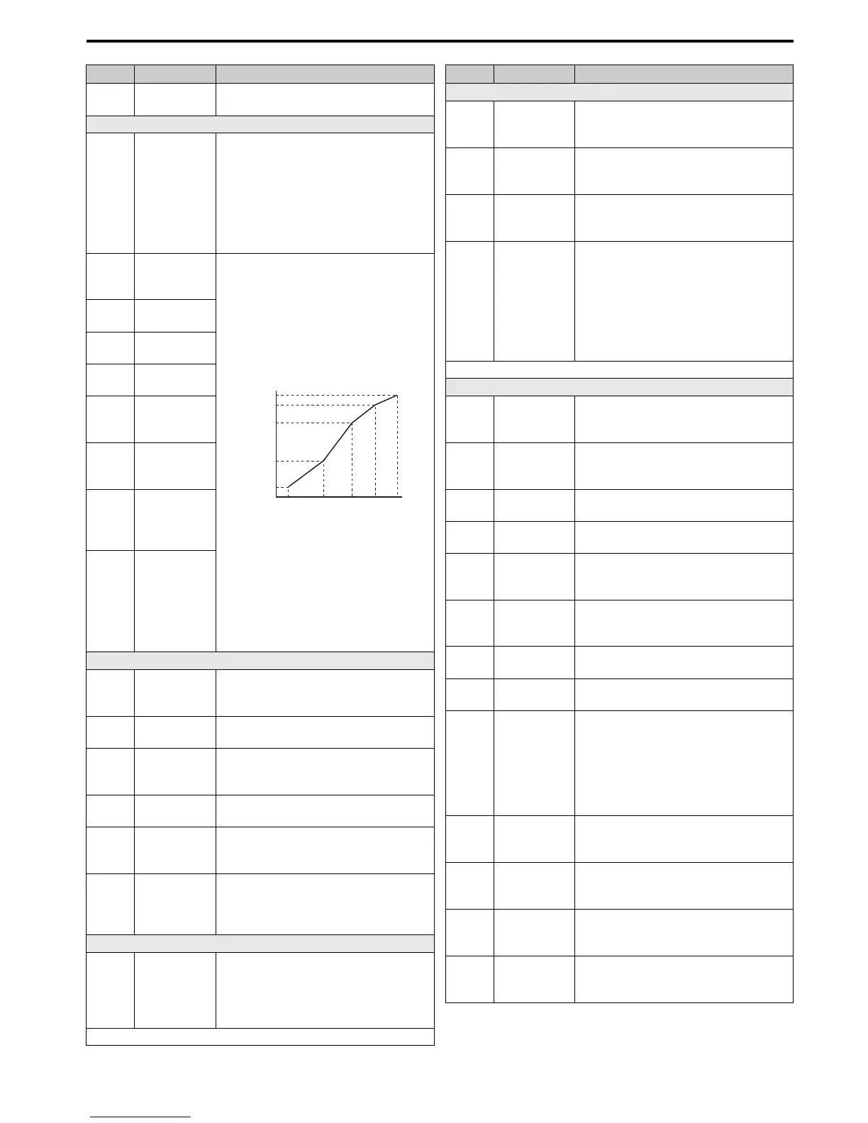
To set linear V/f characteristics, set the
same values for E1-07 and E1-09. In this
case, the setting for E1-08 will be
disregarded. Ensure that the four
frequencies are set according to these rules:
E1-09 ≤ E1-07 < E1-06 ≤ Ε1−11 ≤ E1-04
Note: Some parameters may not be
available depending on the control mode.
• E1-07, E1-08 and E-10 are available only
in the following control modes: V/f
Control, V/f with PG, Open Loop Vector.
• E1-11, E1-12 and E-13 are available only
in the following control modes: V/f
Control, V/f with PG, Open Loop Vector,
Closed Loop Vector.
E1-05
Maximum
Vo l t age
E1-06
Base
Frequency
E1-07
Middle Output
Frequency
E1-08
Middle Output
Frequency
Vo l t age
E1-09
Minimum
Output
Frequency
E1-10
Minimum
Output
Frequency
Vo l t age
E1-13 Base Voltage
Motor 1 Parameters
E2-01
Motor Rated
Current
Sets the motor nameplate full load current in
Amps. Automatically set during
Auto-Tuning.
E2-02
Motor Rated
Slip
Sets the motor rated slip. Automatically set
during Auto-Tuning.
E2-03
Motor
No-Load
Current
Sets the no-load current for the motor.
Automatically set during Auto-Tuning.
E2-04
Number of
Motor Poles
Sets the number of motor poles.
Automatically set during Auto-Tuning.
E2-05
Motor
Line-to-Line
Resistance
Sets the phase-to-phase motor resistance.
Automatically set during Auto-Tuning.
E2-06
Motor Leakage
Inductance
Sets the voltage drop due to motor leakage
inductance as a percentage of motor rated
voltage. Automatically set during
Auto-Tuning.
Multi-Function Digital Inputs
H1-01 to
H1-08
Multi-Function
Digital Input
Terminal S1 to
S8 Function
Selection
Selects the function of terminals S1 to S8.
Note: Major functions are listed at the end of the table.
No. Name Description
Output Voltage (V)
Frequency (Hz)
E1-05
E1-12
E1-13
E1-08
E1-10
E1-09 E1-07 E1-06 E1-11 E1-04
Multi-Function Digital Outputs
H2-01
Terminal M1-
M2 function
selection
Set the function for the relay output M1-
M2.
H2-02
Terminal M3-
M4 function
selection
Sets the function for the relay output M3-
M4.
H2-03
Terminal M5-
M6 function
selection
Sets the function for the relay output M5-
M6.
H2-06
Watt Hour
Output Unit
Selection
Outputs a 200 ms pulse signal when the
watt-hour counter increases by the units
selected.
0: 0.1 kWh units
1: 1 kWh units
2: 10 kWh units
3: 100 kWh units
4: 1000 kWh units
Note: Major functions are listed at the end of the table.
Multi-Function Analog Inputs
H3-01
Terminal A1
Signal Level
Selection
0: 0 to 10 V
1: –10 to 10 V
H3-02
Terminal A1
Function
Selection
Sets the function of terminal A1.
H3-03
Terminal A1
Gain Setting
Sets the level of the input value selected in
H3-02 when 10 V is input at terminal A1.
H3-04
Terminal A1
Bias Setting
Sets the level of the input value selected in
H3-02 when 0 V is input at terminal A1.
H3-05
Terminal A3
Signal Level
Selection
0: 0 to 10 V
1: –10 to 10 V
H3-06
Terminal A3
Function
Selection
Sets the function of terminal A3.
H3-07
Terminal A3
Gain Setting
Sets the level of the input value selected in
H3-06 when 10 V is input at terminal A3.
H3-08
Terminal A3
Bias Setting
Sets the level of the input value selected in
H3-06 when 0 V is input at terminal A3.
H3-09
Terminal A2
Signal Level
Selection
0: 0 to 10 V
1: –10 to 10 V
2: 4 to 20 mA
3: 0 to 20 mA
Note: Use DIP switch S1 to set input
terminal A2 for a current or a voltage input
signal.
H3-10
Terminal A2
Function
Selection
Sets the function of terminal A2.
H3-11
Terminal A2
Gain Setting
Sets the level of the input value selected in
H3-10 when 10 V (20 mA) is input at
terminal A2.
H3-12
Terminal A2
Bias Setting
Sets the level of the input value selected in
H3-10 when 0 V (0 or 4 mA) is input at
terminal A2.
H3-13
Analog Input
Filter Time
Constant
Sets a primary delay filter time constant for
terminals A1, A2, and A3. Used for noise
filtering.
No. Name Description