3 Electrical Installation
YASKAWA ELECTRIC TOEP C710616 27D YASKAWA AC Drive - A1000 Quick Start Guide 17
Control Circuit Terminal Functions
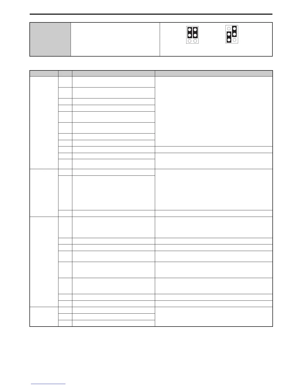
S5 Terminal FM/AM Signal Selection
Type No. Terminal Name (Function) Function (Signal Level) Default Setting
Multi-Function
Digital Inputs
S1
Multi-function input 1 (Closed: Forward run,
Open: Stop)
Photocoupler
24 Vdc, 8 mA
Use the wire link between terminals SC and SN or SC and SP to select
between sinking, sourcing mode, and the power supply.
S2
Multi-function input 2 (Closed: Reverse run,
Open: Stop)
S3
Multi-function input 3 (External fault, N.O.)
S4
Multi-function input 4 (Fault reset)
S5
Multi-function input 5 (Multi-step speed
reference 1)
S6
Multi-function input 6 (Multi-step speed
reference 2)
S7
Multi-function input 7 (Jog reference)
S8
Multi-function input 8 (External baseblock)
SC
Multi-function input common –
SN Multi-function input 0 V 24 Vdc power supply for digital inputs, 150 mA max (if no digital
input option DI-A3 is used)
Never short terminals SP and SN as doing so will damage the drive.
SP Multi-function input 24 Vdc
Safe Disable
Inputs
H1
Safe Disable input 1
24 Vdc, 8 mA
One or both open: Drive output disabled
Both closed: Normal operation
Internal impedance: 3.3 kΩ
Off time of at least 1 ms
Disconnect the wire jumpers shorting terminals H1, H2, and HC to
use the Safe Disable inputs. Set the S3 jumper to select between
sinking, sourcing mode, and the power supply.
H2
Safe Disable input 2
HC
Safe Disable function common Safe disable function common
Analog Inputs /
Pulse Train
Input
RP
Multi-function pulse train input (Frequency
reference)
Input frequency range: 0 to 32 kHz
Signal Duty Cycle: 30 to 70%
High level: 3.5 to 13.2 Vdc, low level: 0.0 to 0.8 Vdc
Input impedance: 3 kΩ
+V
Power supply for analog inputs 10.5 Vdc (max allowable current 20 mA)
-V
Power supply for analog inputs -10.5 Vdc (max allowable current 20 mA)
A1
Multi-function analog input 1 (Frequency
reference bias)
-10 to 10 Vdc, 0 to 10 Vdc (input impedance: 20 kΩ)
A2
Multi-function analog input 2 (Frequency
reference bias)
-10 to 10 Vdc, 0 to 10 Vdc (input impedance: 20 kΩ)
4 to 20 mA, 0 to 20 mA (input impedance: 250
Ω)
Voltage or current input must be selected by DIP switch S1 and H3-09
A3
Multi-function analog input 3 / PTC Input
(Auxiliary frequency reference)
-10 to 10 Vdc, 0 to 10 Vdc (input impedance: 20 kΩ)
Use switch S4 on the control terminal board to select between analog
input or PTC input. If PTC is selected, set H3-06 = E.
AC
Frequency reference common 0 V
E (G)
Ground for shielded lines and option cards –
Fault Relay
MA
N.O.
30 Vdc, 10 mA to 1 A; 250 Vac, 10 mA to 1 A
Minimum load: 5 Vdc, 10 mA
MB
N.C. output
MC
Fault output common
AM
FM
V
I
V
I
AM
FM
FM/AM: Voltage Output FM: Current Output
AM: Voltage Output
...