6 Parameter Table
YASKAWA ELECTRIC TOEP C710616 27D YASKAWA AC Drive - A1000 Quick Start Guide 29
L3-05
Stall
Prevention
Selection
during Run
0: Disabled. Drive runs at a set frequency. A
heavy load may cause speed loss.
1: Decel time 1. Uses the deceleration
time set to C1-02 while Stall Prevention is
performed.
2: Decel time 2. Uses the deceleration time
set to C1-04 while Stall Prevention is
performed.
L3-06
Stall
Prevention
Level during
Run
Enabled when L3-05 is set to 1 or 2. 100%
is equal to the drive rated current.
Induction Motor Auto-Tuning
T1-01
Auto-Tuning
Mode
Selection
0: Rotational Auto-Tuning
1: Stationary Auto-Tuning 1
2: Stationary Auto-Tuning for Line-to-Line
Resistance
3: Rotational Auto-Tuning for V/f Control
(necessary for Energy Savings and Speed
Estimation Speed Search)
4: Stationary Auto-Tuning 2
8: Inertia Tuning (perform Rotational Auto-
Tuning prior to Inertia Tuning)
9: ASR Gain Tuning (perform Rotational
Auto-Tuning prior to ASR Gain Auto-
Tuning)
T1-02
Motor Rated
Power
Sets the motor rated power as specified on
the motor nameplate.
T1-03
Motor Rated
Vo l t age
Sets the motor rated voltage as specified on
the motor nameplate.
T1-04
Motor Rated
Current
Sets the motor rated current as specified on
the motor nameplate.
T1-05
Motor Base
Frequency
Sets the rated frequency of the motor as
specified on the motor nameplate.
T1-06
Number of
Motor Poles
Sets the number of motor poles as specified
on the motor nameplate.
T1-07
Motor Base
Speed
Sets the rated speed of the motor as
specified on the motor nameplate.
T1-08
PG Number of
Pulses Per
Revolution
Set the number of pulses per revolution for
the PG being used (pulse generator or
encoder).
T1-09
Motor No-
Load Current
(Stationary
Auto-Tuning)
Sets the no-load current for the motor.
After setting the motor capacity to T1-02
and the motor rated current to T1-04, this
parameter will automatically display the no-
load current for a standard 4 pole Yaskawa
motor. Enter the no-load current as
indicated on the motor test report.
T1-10
Motor Rated
Slip
(Stationary
Auto-Tuning)
Sets the motor rated slip.
After setting the motor capacity to T1-02,
this parameter will automatically display the
motor slip for a standard 4 pole Yaskawa
motor. Enter the motor slip as indicated on
the motor test report.
T1-11
Motor Iron
Loss
Sets the iron loss for determining the
Energy Saving coefficient.
The value is set to E2-10 (motor iron loss)
set when the power is cycled. If T1-02 is
changed, a default value appropriate for the
motor capacity that was entered will appear.
No. Name Description
Monitor Description
U1-01 Frequency Reference (Hz)
U1-02 Output Frequency (Hz)
U1-03 Output Current (A)
U1-05 Motor Speed (Hz)
U1-06 Output Voltage Reference (Vac)
U1-07 DC Bus Voltage (Vdc)
U1-08 Output Power (kW)
U1-09 Torque Reference (% of motor rated torque)
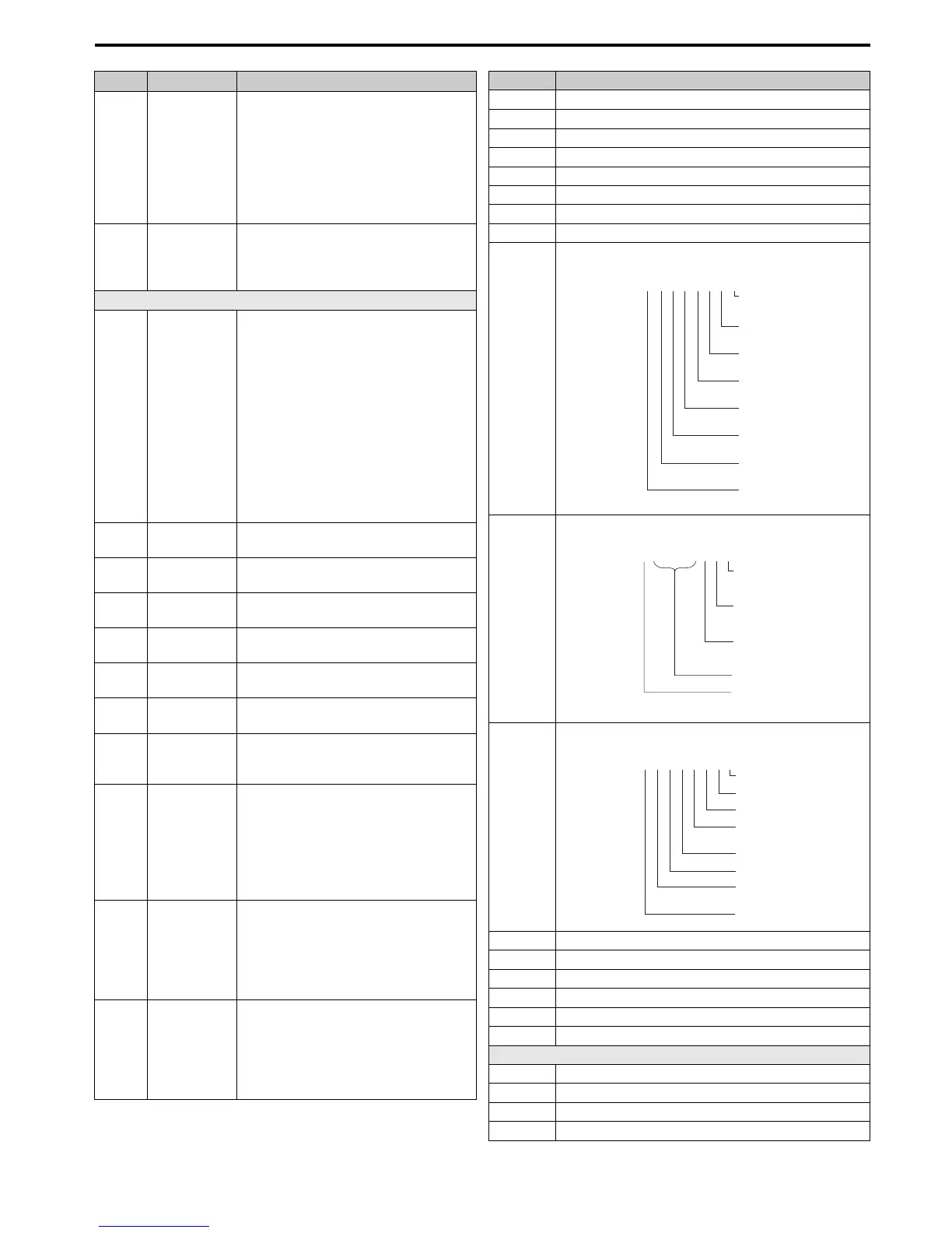
U1-10
Displays the input terminal status.
U1-11
Displays the output terminal status.
U1-12
Verifies the drive operation status.
U1-13 Terminal A1 Input Level
U1-14 Terminal A2 Input Level
U1-15 Terminal A3 Input Level
U1-16 Output Frequency after Soft Starter
U1-18 oPE Fault Parameter
U1-24 Input Pulse Monitor
Fault Trace
U2-01 Current Fault
U2-02 Previous Fault
U2-03 Frequency Reference at Previous Fault
U2-04 Output Frequency at Previous Fault
U1
-
10=
00000000
Digital input 1
(terminal S1 enabled)
Digital input 2
(terminal S2 enabled)
Digital input 3
(terminal S3 enabled)
Digital input 4
(terminal S4 enabled)
Digital input 5
(terminal S5 enabled)
Digital input 6
(terminal S6 enabled)
Digital input 7
(terminal S7 enabled)
Digital input 8
(terminal S8 enabled)
1
1
1
1
1
1
1
1
U1
-
11=
00000000
Multi-Function
Digital Output
(terminal M1-M2)
Digital Output
(terminal M3-M4)
Digital Output
(terminal M5-M6)
Multi-Function
Multi-Function
Not Used
Fault Relay
(terminal MA-MC closed
MA-MC open)
1
1
1
1
U1
-
12=
00000000
During run
During zero-speed
During REV
During fault reset
signal input
During speed agree
Drive ready
During alarm
detection
During fault detection
1
1
1
1
1
1
1
1