,all
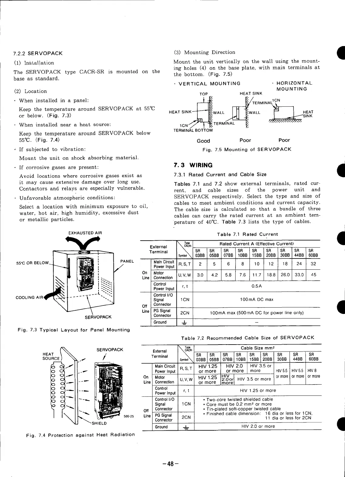
(3) MountingDirection •
7.2.2
SERVOPACK
(i) Installation Mount the unitverticallyon the wall usingthe mount-
ing holes (4) on the base plate, with main terminals at
The SERVOPACK type CACR-SR is mounted on the the bottom. (Fig. 7.5)
base as standard.
• VERTICAL MOUNTING • HORIZONTAL
MOUNTING
(2) Location TOP HEAT SINK
Keep the temperature around SERVOPACK at 55°C
HEAT SINK-'-T'-_I_/WALL I II _WALL r-" I HEAT
or below. (Fig. 7.3) L- I1_ _ .._ I .._SINK
j2LLr. TERM 'L
• When installed near a heat source: 1CN/ _ _ ..... F,
TERMINAL BOTTOM
Keep the temperature around SERVOPACK below
55°C. (Fig. 7.4) Good Poor Poor
' If subjected to vibration: Fig. 7.5 Mounting of SERVOPACK
Mount the unit on shock absorbing material.
• If corrosive gases are present: 7.3 WIRING •
Avoid locations where corrosive gases exist as 7.3.1 Rated Current and Cable Size
1
it may cause extensive damage over long use. Tables 7.1 and 7.2 show external terminals, rated cur-
Contactors add relays are especially vulnerable.
rent, and cable sizes of the power unit and
• Unfavorable atmospheric conditions: SERVOPACK respectively. Select the type and size of
cables to meet ambient conditions and current capacity.
Select a location with minimum exposure to oil,
The cable size is calculated so that a bundle of three
water, hot air, high humidity, excessive dust
cables can carry the rated current at an ambient tem-
or metallic particles, perature of 40°C. Table 7.3 lists the type of cables.
EXHAUSTED AIR Table 7.1 Rated Current
y T_ RatedCurrent A (Effective Current)
I
External CACR-
_ ,_ Terminal SR SR SR SR SR SR SR SR SR
' 038B 0EBB 07BB 10BB 15B8 20BB 3OBB 44BB 60BB
55"C OR BELOW_ PANEL Main Circuit R, S, T 2 5 6 8 10 12 18 24 32
/" Power Input
i On Motor
f
" • - Line Connection U,V,W 3.0 4.2 5.8 7.6 11.7 18.8 26.0 33.0 45
.__ Control
Power Input r, t O.5A
COOLING AIR" Control I/0
Signal 1CN 100 mA DC max
Off Connector 9
Line PG Signal 2CN 100mA max (500mA DC for power line only)
SERVOPACK Connector
Ground __J=L._
Fig. 7.3 Typical Layout for Panel Mounting
Table 7.2 Recommended Cable Size of SERVOPACK
SERVOPACK External T_R_T_R" Cable Size mm 2
/ s_l'_ 03B8 07BB 1S;BB SR SR SR SR
HEAT SR SR SR SR
SOURCE Terminal
0EBB 10BS 20BB 30BB 448B 60B8
Main Circuit R,S, T HIV 1.25 HIV 2.0 HIV 3.5 or
Power Input or more or more more HIV5.5 HIV5.5 HIV8
On Motor U,V,W HIV1.25 HIV ormore ormore ormore
2.0or HIV 3.5 or more
Line Connection or more more
Control
PowerInput r, t HIV 1.25 or more
Control I/0 • Two-core twisted shielded cable
• Signal 1CN • Core must be 0.2 mm 2 or more
Off Connector • Tin-plated soft-copper twisted cable
586-25 Line PG Signal 2CN • Finished cable dimension: 16 alia or less for 1CN,
SHIELD Connector 11 diaor lessfor 2CN
Ground _ HIV 2.0 or more
Fig. 7.4 Protection against Heat Radiation
-48-