7-12
Alarm Detection
Alarms are detected as a type of Inverter protection function that do not operate the fault contact output. The
system will automatically returned to its original status once the cause of the alarm has been removed.
The Digital Operator display blinks and an alarm is sent from the multi-function outputs (H2-01 to H2-03) if
selected.
When an alarm occurs, take appropriate countermeasures according to the table below.
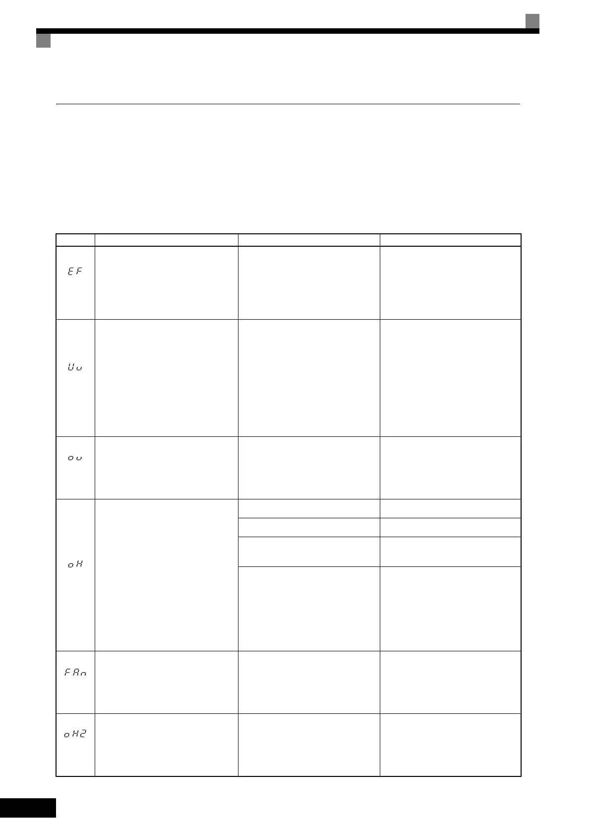
Table 7.3 Alarm Displays and Processing
Display Meaning Probable causes Corrective Actions
(blink-
ing)
Forward/Reverse Run Commands
Input Together
Both the forward and Reverse Run
Commands have been ON for more
than 0.5 s.
-
Check the sequence of the forward
and Reverse Run Commands.
Since the rotational direction is
unknown, the motor will be deceler-
ated to a stop when this minor fault
occurs.
(blink-
ing)
Main Circuit Undervoltage
The following conditions occurred
when there was no Run signal.
• The main circuit DC voltage was
below the Undervoltage Detection
Level Setting (L2-05).
• The surge current limiting mag-
netic contactor opened.
• The control power supply voltage
when below the CUV level.
See causes for UV1, UV2, and UV3
faults in the previous table.
See corrective actions for UV1, UV2,
and UV3 faults in the previous table.
(blink-
ing)
Main Circuit Overvoltage
The main circuit DC voltage exceeded
the overvoltage detection level.
200 V Class: Approx. 410 V
400 V Class: Approx. 820 V
The power supply voltage is too high.
Decrease the voltage so it's within
specifications.
(blink-
ing)
Cooling Fin Overheating
The temperature of the Inverter's cool-
ing fins exceeded the setting in L8-02.
The ambient temperature is too high. Install a cooling unit.
There is a heat source nearby. Remove the heat source
The Inverter cooling fan has stopped.
Replace the cooling fan. (Contact
your Yaskawa representative.)
• A short-circuit between +V, −V, a n d
AC terminals occurred.
• Overload in the control circuit ter-
minal.
• Make sure that incorrect wiring has
not been done.
• Check the resistance and wiring for
the frequency setting potentiome-
ter, etc. (Check that the current for
terminals +V and –V is 20 mA or
less.)
(blink-
ing)
Inverter’s Cooling Fan Fault
An Inverter’s cooling fan fault was
detected.
This fault is detected when L8-32 is
set to 0.
The Inverter’s cooling fan has
stopped.
Replace the cooling fan. (Contact our
sales representative.)
(blink-
ing)
Inverter Overheating Pre-alarm
An OH2 alarm signal (Inverter over-
heating alarm signal) was input from a
multi-function input terminal (S3 to
S8).
-
Clear the multi-function input termi-
nal's overheating alarm input.

 Loading...