2-14
Standard Connection Diagrams
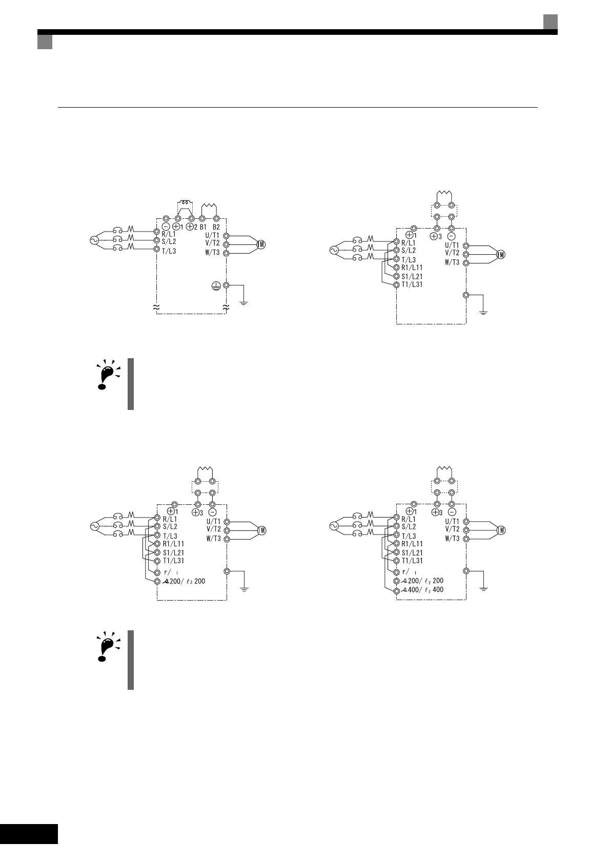
Standard Inverter connection diagrams are shown in Fig 2.5. The connections depend on the Inverter capacity.
Control power is supplied internally from the main circuit DC power supply for all Inverter models.
Fig 2.5 Main Circuit Terminal Connections
CIMR-F7A20P4 to 2018 and 40P4 to 4018
Be sure to remove the short-circuit bar before connecting the DC
reactor.
CIMR-F7A2022, 2030, and 4022 to 4055
The DC reactor is built in.
IMPORTANT
When connecting a separately-installed type Braking Unit (model CDBR), connect the B1 terminal of the
Inverter to the + terminal of the Braking Unit and connect the − terminal of the Inverter to the − terminal of the
Braking Unit. The B2 terminal is not used in this case.
CIMR-FA2037 to 2110 CIMR-F7A4075 to 4300
IMPORTANT
If a Braking Unit or a Braking Resistor Unit is connected to a wrong terminal, the Inverter, Braking Unit, or
Braking Resistor Unit can be damaged.
Refer to FOR VARISPEED-600 SERIES INVERTER BRAKING UNIT BRAKING RESISTOR UNIT
INSTRUCTIONS (TOBPC720600000) for connecting the Inverter with a Braking Unit or a Braking Resistor
Unit.
DC reactor
(optional)
3-phase 200
VAC (400 VAC)
Braking Resistor
Unit (optional)
Braking Unit
(optional)
Braking Resistor
Unit (optional)
3-phase 200
VAC (200 VAC)
l
3-phase
200 VAC
Braking Unit
(optional)
Braking Resistor
Unit (optional)
l
3-phase
400 VAC
Braking Unit
(optional)
Braking Resistor
Unit (optional)

 Loading...