Exterior and Mounting Dimensions
1-7
Exterior and Mounting Dimensions
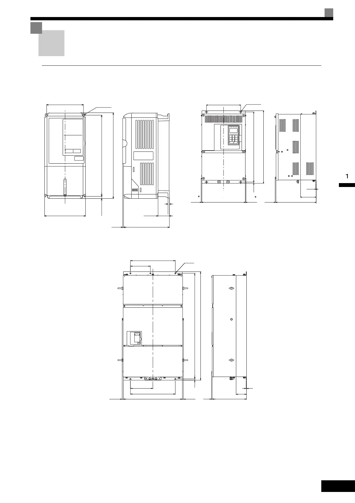
Open Chassis Inverters (IP00)
Exterior diagrams of the Open Chassis Inverters are shown below.
Fig 1.6 Exterior Diagrams of Open Chassis Inverters
W
W1
3
H1H2
D
H
D1
4-d
t1
200 V Class Inverters of 22 or 110 kW
400 V Class Inverters of 22 to 160 kW
W
W1
4-d
H2
(5)
D1
D
H1
H
t1
(5)(5)
200 V/400 V Class Inverters of 0.4 to 18.5 kW
* (10) for 200 V Class Inverters of 37 to 110 kW or 400 V Class Invert-
ers of 75 to 160 kW.
400 V Class Inverters of 185 to 300 kW
6-d
H1
H
t1
H2
W
W1
W3
W2
W1
D1
D(5)
(15) (15)

 Loading...