EasyManua.ls Logo

YASKAWA CIMR-F7A User Manual

YASKAWA CIMR-F7A
478 pages
To Next Page IconTo Next Page
Page #1 background imageLoading...
Page #1 background image
YASKAWA
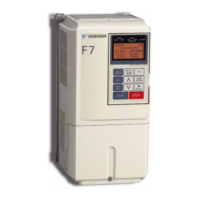
Varispeed F7
INSTRUCTION MANUAL
YA S K A WA
MANUAL NO. TOE-S616-55.1D
GENERAL PURPOSE INVERTER (CURRENT VECTOR CONTROL)
MODEL
:
CIMR-F7A
Upon receipt of the product and prior to initial operation, read these instructions
thoroughly, and retain for future reference.
200V CLASS 0.4 to 110kW (1.2 to 160kVA)
400V CLASS 0.4 to 300kW (1.4 to 510kVA)

Table of Contents

Questions and Answers:

YASKAWA CIMR-F7A Specifications

General IconGeneral
Input Voltage200-240V AC, 380-480V AC, 500-600V AC
Output VoltageMatches Input Voltage
Horsepower Range0.5 HP to 300 HP
Power Range0.4 kW to 220 kW
Frequency Range0.1 Hz to 400 Hz
Control MethodV/f Control
Overload Capacity150% for 60 seconds
Protection FunctionsOvercurrent, Overvoltage, Undervoltage, Overheating, Short Circuit, Ground Fault
Communication OptionsRS-485, Modbus, DeviceNet, Profibus, Ethernet
Operating Temperature-10°C to 50°C
Storage Temperature-20°C to 65°C
Humidity5% to 95% (non-condensing)
Cooling MethodFan Cooled
Enclosure RatingIP20

Summary

Preface

General Precautions

General advice for safe and proper use of the inverter, including handling covers and illustrations.

Safety Information

WARNING

Indicates precautions that, if not heeded, could possibly result in loss of life or serious injury.

CAUTION

Indicates precautions that, if not heeded, could result in relatively serious or minor injury, damage to the product, or faulty operation.

IMPORTANT

Indicates important information that should be memorized.

Safety Precautions

Confirmations upon Delivery

Actions to take upon receiving the inverter to check for damage or missing components.

Installation

Precautions and guidelines for safely installing the inverter.

Wiring

Essential safety precautions to follow when wiring the inverter and its components.

Setting User Constants

Setting the Autotuning Mode

Details on selecting and configuring the autotuning mode for motor parameter setup.

Trial Operation

Trial Operation Procedures

Details the step-by-step procedure for conducting trial operation.

Basic Settings

Lists essential constants that must be set before trial operation.

Settings for the Control Methods

Explains how to make settings according to the selected control method and autotuning.

Maintenance and Inspection

Periodic Inspection

Lists items to check during periodic maintenance.

Cooling Fan Replacement Outline

Provides instructions for replacing cooling fans in various inverter models.

Other

Do not attempt to modify or alter the Inverter

Warning against unauthorized modifications to prevent electrical shock or injury.

Warning Information and Position

Warning Information

Highlights critical warnings about electrical shock risks and the need to read the manual.

Warranty Information

Free Warranty Period and Scope

Details the warranty coverage, period, and what is included or excluded.

Restrictions

Outlines limitations on product use, especially concerning life-threatening applications.

Registered Trademarks

Before Reading This Manual

Advises users to check the inverter nameplate for specific model details.

1 Handling Inverters

Varispeed F7 Introduction

Provides an overview of the Varispeed F7 series, its applications, and models.

Confirmations upon Delivery

Details the checks to perform immediately after receiving the inverter.

Component Names

Identifies the external appearance and names of the inverter's components.

Exterior and Mounting Dimensions

Shows exterior diagrams and dimensions for different inverter types.

Enclosed Wall-mounted Inverters [NEMA1 (Type 1)]

Describes the specifications and protection of enclosed wall-mounted inverter types.

Checking and Controlling the Installation Site

Guidelines for selecting and maintaining an optimal installation site for the inverter.

Installation Orientation and Space

Recommends vertical installation and specifies required clearances for heat dissipation.

Removing and Attaching the Terminal Cover

Provides instructions for safely removing and reattaching the terminal cover.

Removing/Attaching the Digital Operator and Front Cover

Details the process of removing and attaching the digital operator and front cover.

Removing and Attaching the Protection Cover

Details the procedure for removing and attaching top and bottom protection covers.

2 Wiring

Connection Diagram

Shows the overall connection diagram of the inverter.

Wiring Main Circuit Terminals

Provides specifications for applicable wire sizes and closed-loop connectors.

Wiring Control Circuit Terminals

Details wire sizes and closed-loop connectors for control circuit terminals.

Installing and Wiring Option Boards

Describes how to install and wire various option boards.

3 Digital Operator and Modes

Digital Operator

Explains the displays and functions of the digital operator.

Modes

Describes the inverter's operating modes and how to switch between them.

Drive Mode

Explains how the inverter can be operated and its status monitored in drive mode.

Quick Programming Mode

Allows monitoring and setting of constants for trial operation.

Advanced Programming Mode

Allows monitoring and setting of all inverter constants.

Verify Mode

Used to display and set constants changed from default settings.

Autotuning Mode

Automatically tunes and sets motor constants.

4 Trial Operation

Overview of Trial Operation Procedure

Presents a flowchart for performing trial operation and setting basic constants.

Trial Operation Procedures

Details the step-by-step procedure for conducting trial operation.

Basic Settings

Lists essential constants that must be set before trial operation.

Settings for the Control Methods

Explains how to make settings according to the selected control method and autotuning.

5 User Constants

User Constant Descriptions

Explains the structure and meaning of user constant tables.

Digital Operation Display Functions and Levels

Shows the digital operator display hierarchy.

User Constants Settable in Quick Programming Mode

Lists user constants required for inverter operation that can be set in quick programming mode.

6 Constant Settings by Function

Application and Overload Selections

Explains how to select overload settings based on the application.

Frequency Reference

Explains methods for inputting the frequency reference.

Run Command

Explains input methods for the Run Command.

Stopping Methods

Explains methods for stopping the Inverter.

Acceleration and Deceleration Characteristics

Explains the acceleration and deceleration characteristics.

Adjusting Frequency References

Explains methods for adjusting frequency references.

Speed Limit (Frequency Reference Limit Function)

Explains how to limit the motor speed.

Improved Operating Efficiency

Explains functions for improving motor operating efficiency.

Machine Protection

Explains functions for protecting the machine.

Continuing Operation

Explains functions for continuing or automatically restarting Inverter operation.

Inverter Protection

Explains functions for protecting the Inverter and the braking resistor.

Input Terminal Functions

Explains input terminal functions and setting operating methods.

Output Terminal Functions

Explains output terminal functions, which set output methods.

Monitor Constants

Explains analog monitor and pulse monitor constants.

7 Troubleshooting

Protective and Diagnostic Functions

Describes the alarm functions of the Inverter.

Fault Detection

Explains how the inverter detects faults and the corresponding actions.

Alarm Detection

Describes alarm functions that do not operate the fault contact output.

Operation Errors

Explains errors occurring due to invalid settings or contradictions.

Errors During Autotuning

Lists errors that can occur during autotuning.

Errors when Using the Digital Operator Copy Function

Lists errors that can occur when using the copy function.

Troubleshooting

Provides guidance for addressing issues when the inverter and motor do not operate as expected.

If the Motor Does Not Operate

Provides information for when the motor does not operate.

If the Motor Does Not Put Out Torque or If Acceleration is Slow

Provides information for when the motor does not output torque or acceleration is slow.

If the Motor Overheats

Provides information on motor overheating causes and corrective actions.

8 Maintenance and Inspection

Maintenance and Inspection

Describes basic maintenance and inspection for the inverter.

Periodic Inspection

Lists items to check during periodic maintenance.

Cooling Fan Replacement Outline

Provides instructions for replacing cooling fans in various inverter models.

9 Specifications

Standard Inverter Specifications

Lists standard inverter specifications by capacity.

Specifications by Model

Provides specifications categorized by model number.

Common Specifications

Lists specifications applicable to both 200V and 400V Class inverters.

Specifications of Options and Peripheral Devices

Details specifications for available options and peripheral devices.

10 Appendix

Varispeed F7 Control Methods

Details the Varispeed F7 Inverter's control methods and their features.

Inverter Application Precautions

Provides precautions for selecting, installing, setting, and handling inverters.

Motor Application Precautions

Offers precautions for motor applications when using the inverter.

Conformance to UL Standard

Gives points regarding conformance to UL standards.

Conformance to CE Markings

Provides points regarding conformance to CE markings.

Wiring Examples

Shows wiring examples for various connections.

User Constants

Lists user constants and their factory settings.

Related product manuals