User Constant Tables
5-81
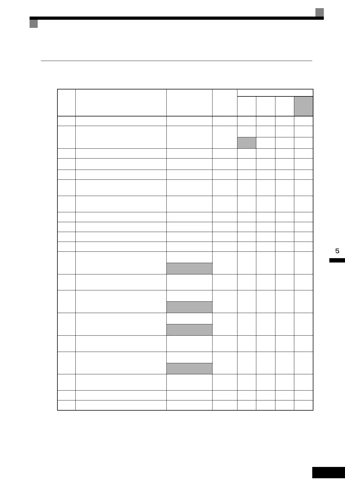
Factory Settings that Change with the Control Method (A1-02)
The factory settings of the following user constants will change if the control method (A1-02) is changed.
* 1. For Inverters with a capacity of 55 kW or more, the factory setting is 2.00 for open-loop vector control and 0.05 for flux vector control.
* 2. When C6-01 = 0, the upper limit is 150.0.
* 3. Settings vary as shown in the following tables depending on the Inverter capacity and E1-03.
* 4. The settings shown are for 200 V Class Inverters. The values will double for 400 V Class Inverters.
* 5. When C6-01 = 1, the upper limit is 400.0.
* 6. C6-01 = 1:120%, C6-01 = 0:150%
* 7. 1000 ms for Inverters of 200 V Class 30 to 110 kW and 400 V Class 55 to 300 kW.
Con-
stant
Number
Name Setting Range Unit
Factory Setting
V/f Con-
trol
A1-02=0
V/F with
PG
A1-02=1
Open
Loop
Vector
A1-02=2
Flux
Vector
A1-02=3
b3-01 Speed search selection 0 to 3 1 2 3 2 -
b3-02 Speed search operating current 0 to 200 1%
120
*6
- 100 -
150
*6
b8-02 Energy-saving gain 0.0 to 10.0 0.1 - - 0.7 1.0
b8-03 Energy-saving filter time constant 0.00 to 10.00 0.01 s - -
0.50
*1
0.01
*1
C3-01 Slip compensation gain 0.0 to 2.5 0.1 0.0 - 1.0 1.0
C3-02
Slip compensation primary delay time
constant
0 to 10000 1 ms 2000 - 200 -
C4-02
Torque compensation primary delay time
constant
0 to 10000 1 ms
200
*7
200
*7
20 -
C5-01 ASR proportional (P) gain 1 0 to 300.00 0.01 - 0.20 - 20.00
C5-02
ASR integral (I) time 1 0.000 to 10.000 0.001 s - 0.200 - 0.500
C5-03 ASR proportional (P) gain 2 0.00 to 300.00 0.01 - 0.02 - 20.00
C5-04 ASR integral (I) time 2 0.000 to 10.000 0.001 s - 0.050 - 0.500
E1-04
E3-02
Max. output frequency (FMAX)
40.0 to 400.0
*2
0.1 Hz
60.0
*3
60.0
*3
60.0 60.0
40.0 to 300.0
*5
E1-05
E3-03
Max. voltage (VMAX)
*4
0.0 to 255.0
(0.0 to 510.0)
0.1 V
200.0
*3
200.0
*3
200.0 200.0
E1-06
E3-04
Base frequency (FA)
0.0 to 400.0
*2
0.1 Hz
60.0
*3
60.0
*3
60.0 60.0
0.0 to 300.0
*5
E1-07
E3-05
Mid. output frequency (FB)
0.0 to 400.0
*2
0.1 Hz
3.0
*3
3.0
*3
3.0 0.0
0.0 to 300.0
*5
E1-08
E3-06
Mid. output frequency voltage (VC)
*4
0.0 to 255.0
(0.0 to 510.0)
0.1 V
15.0
*3
15.0
*3
11.0 0.0
E1-09
E3-07
Min. output frequency (FMIN)
0.0 to 400.0
*2
0.1 Hz
1.5
*3
1.5
*3
0.5 0.0
0.0 to 300.0
*5
E1-10
E3-08
Min. output frequency voltage (VMIN)
*4
0.0 to 255.0
(0.0 to 510.0)
0.1 V
9.0
*3
9.0
*3
2.0 0.0
F1-09 Overspeed detection delay time 0.0 to 2.0 0.1 s - 1.0 - 0.0
L8-18 Soft CLA selection 0, 1 1 1 1 1 0

 Loading...