Wiring Control Circuit Terminals
2-25
Control Circuit Terminal Functions
The functions of the control circuit terminals are shown in Table 2.11. Use the appropriate terminals for the
correct purposes.
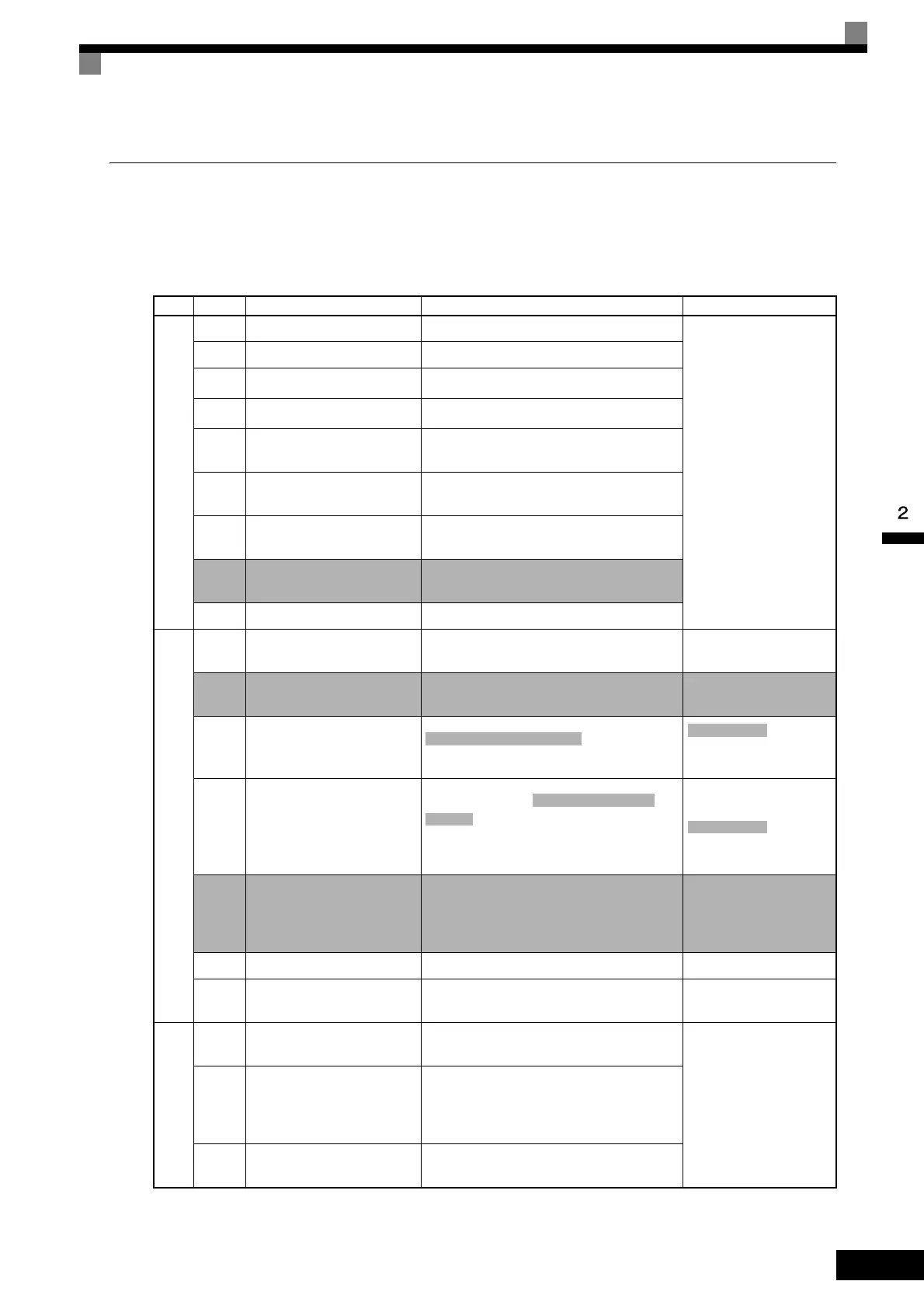
Table 2.11 Control Circuit Terminals
Type
No. Signal Name Function Signal Level
Se-
quence
input
signals
S1 Forward Run/Stop Command Forward run when ON; stopped when OFF.
24 VDC, 8 mA
Photocoupler isolation
S2 Reverse Run/Stop Command Reverse run when ON; stopped when OFF.
S3
Multi-function input 1
*1
Factory setting: External fault when ON.
S4
Multi-function input 2
*1
Factory setting: Fault reset when ON.
S5
Multi-function input 3
*1
Factory setting: Multi-speed reference 1
effective when ON.
S6
Multi-function input 4
*1
Factory setting: Multi-speed reference 2
effective when ON.
S7
Multi-function input 5
*1
Factory setting: Jog frequency selected when
ON.
S8
Multi-function input 6
*1
Factory setting: External baseblock when
ON.
SC Sequence input common -
Analog
input
signals
+V +15 V power output +15 V power supply for analog references
+15 V
(Max. current: 20 mA)
-V -15 V power output -15 V power supply for analog references
-15 V
(Max. current: 20 mA)
A1
Master speed frequency ref-
erence
0 to +10 V/100%
, 0 to +10
V (Input impedance:
20 kΩ)
A2 Multi-function analog input
4 to 20 mA/100%,
, 0 to +10 V/100%
Factory setting: Added to terminal A1
(H3-09 = 0)
4 to 20 mA (Input imped-
ance: 250 Ω)
, 0 to +10
V (Input impedance:
20 kΩ)
A3 Multi-function analog input
-10 to +10 V/-100 to +100%, 0 to +10 V/
100%
Factory setting: Not used
(H3-05 = 1F)
-10 to +10 V, 0 to +10 V
(Input impedance:
20 kΩ)
AC Analog reference common 0 V -
E(G)
Shield wire, optional ground
line connection point
--
Photo-
coupler
outputs
P1 Multi-function PHC output 1
Factory setting: Zero-speed
Zero-speed level (b2-01) or below when ON.
50 mA max. at 48 VDC
*2
P2 Multi-function PHC output 2
Factory setting: Frequency agreement detec-
tion
Frequency within 2 Hz of set frequency
when ON.
PC
Photocoupler output common
for P1 and P2
-
-10 to +10 V/-100 to 100%
-10 to +10 V
-10 to +10 V/-100 to
+100%
-10 to +10 V

 Loading...