Programming 100
Function: Aux Reference 1
Setting: 2
Function: Aux Reference 2
Setting: 3
Aux reference 1 and aux reference 2 works in conjunction with preset reference 2 and 3. In order for the analog input A2 or A3
to be used as the master frequency reference, the analog input must be set for Aux Reference 1 or Aux Reference 2 and the
digital input programmed for Multi-Step Ref 1 (H1-0x= 3) or Multi-Step Ref 1 (H1-0x= 3), respectively, must be selected by a
contact closure. See parameter d1-xx for details.
Function: Voltage Bias
Setting: 4
Voltage bias boosts the output voltage of the V/f curve as a percentage of motor rated voltage (E1-05).
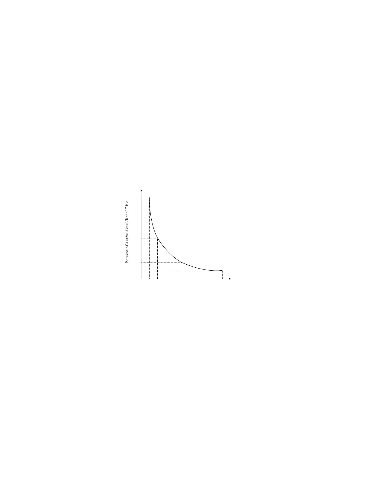
Function: Acceleration / Deceleration Change
Setting: 5
Acc / Dec change functions as a gain for the active acceleration and deceleration time (C1-01 to C1-08).
Fig. 69 Accel / Dece; Time Change
Function: DC Brake Current
Setting: 6
DC brake current allows the analog input level to set the DC injection braking current level as a percentage of Drive rated current.
Function: Overtorque Level
Setting: 7
Overtorque level sets the overtorque/undertorque detection level using the analog input. This works with torque detection
selection 1 (L6-01) and will take the place of the torque detection level 1 (L6-02). For open loop vector and flux vector control
methods (A1-02 = 2 or 3) 100% = motor rated torque. For V/f without PG and V/f with PG (A1-02 = 0 or 1) 100% = Drive
rated current.
0 1 V 2 V 5 V 1 0 V
100%
50%
20%
10%
P
e
r
c
e
n
t
o
f
A
c
t
i
v
e
A
c
c
e
l
/
D
e
c
e
l
T
i
m
e
Analog Input Level
 Loading...


