Programming 48
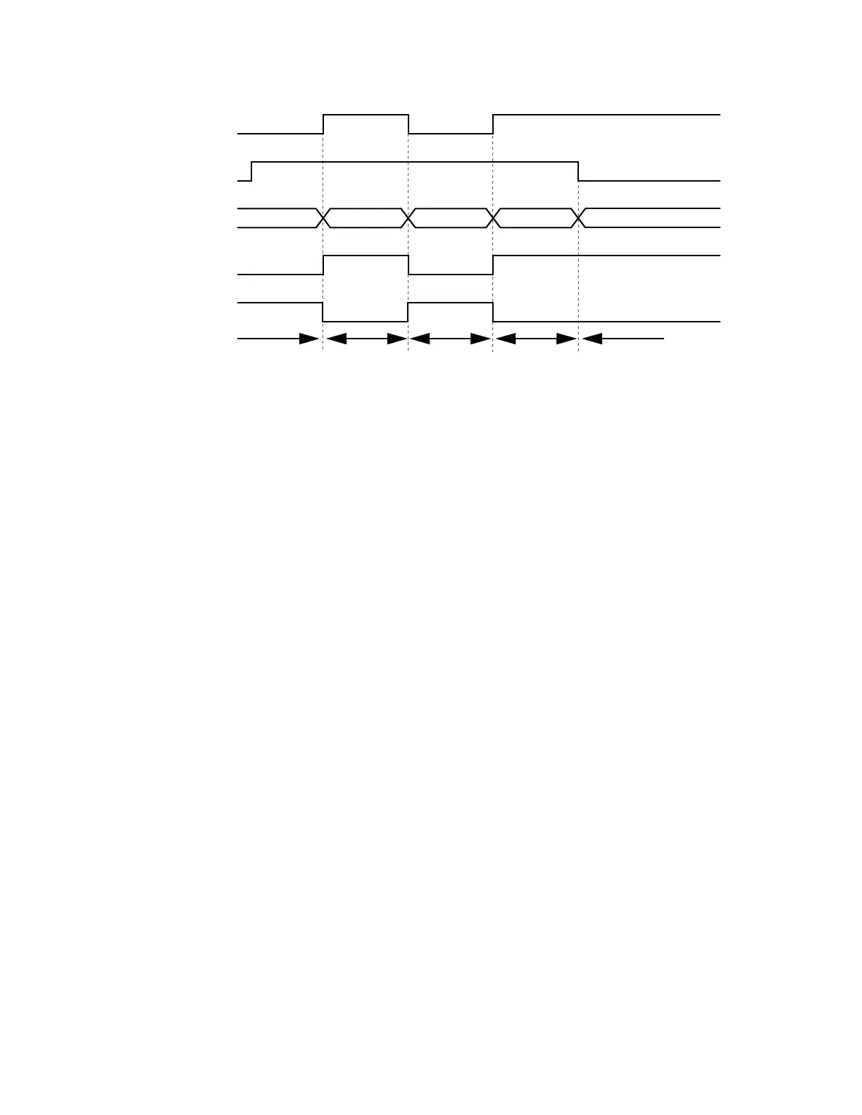
The following figure shows the timing diagram of speed/torque selection.
Fig. 37 Speed / Torque Control Selection Timing Diagram
Timing Diagram Description
When the speed/torque control selection contact is OFF, speed control is activated.
· Speed reference during speed control depends on the frequency reference selection (B1-01) setting. To use terminal A1
or A2 as the master frequency reference, set b1-0l to “l”.
· Torque limit during speed control is the smaller of the absolute value of terminal A3 torque limit, or the values set in the
torque limit parameters (L7-01 to L7-04).
· When a stop command is given during speed control, speed control is maintained and the smaller of the absolute value of
terminal A3 torque limit, or the values set in the torque limit parameters (L7-01 to L7-04), is used as the torque limit.
Then the motor decelerates to stop.
When the speed/torque control selection contact is ON, torque control is activated.
· Speed limit during torque control is the master frequency reference at terminal A1 or A2 when speed limit selection (D5-
03) is set to “1”, and is the speed limit value (D5-04) when D5-03 = “2”, regardless of the frequency reference selection
(B1-01) setting.
· During torque control, the terminal A2 or A3 analog input value becomes the torque reference.
By giving a stop command during torque control, operation changes to speed control automatically, and the motor
decelerates to stop. The torque limit during deceleration to stop becomes the values set in the torque limit parameters
(L7-01 to L7-04).
Note: The control mode actually changes after the speed/torque control selection command changes and after the reference
delay timer (D5-06) elapses. Terminal A1 speed reference/speed limit and the terminal A2 or A3 torque limit/torque
reference are stored in the inverter until the time set to D5-06 elapses.
Speed Control Torque Control
Speed Control Torque Control Speed Control (decel to stop)
OFF ON OFF ON
STOP
RUN
Speed Reference Speed Limit
Speed Reference Speed Limit
Torque Limit Torque Reference
Torque Limit Torque Reference
Speed/Torque
Selection Command
(Terminal S8 Input)
Run Command
Control Method
Terminal A1 Input
Terminal A2 or A3 Input
Sequence
(H3-09 or H3-05 = 13)
 Loading...


