3 Wiring and Connection
3.3.3 Typical Main Circuit Wiring Examples
3-10
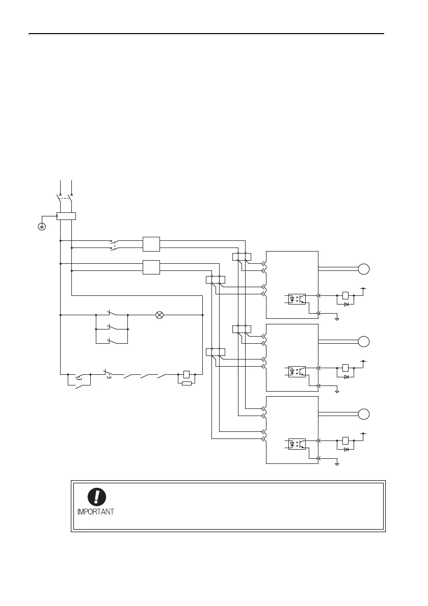
Precautions When Using More Than One SERVOPACK
This section shows an example of the wiring when more than one SERVOPACK is
used and the precautions.
• Wiring Example (Analog model)
The alarm output (ALM) terminals in each SERVOPACK individually operate differ-
ent alarm detection relays: 1Ry, 2Ry, and 3Ry respectively.
When the alarm occurs, the ALM output signal transistor is turned OFF.
8
11
ALM
COM_SG
M
1Ry
1D
+24 V
CN1
CN1
CN3
C2
C1
L2
L1
Insulated AC/DC
converter for main
circuit power supply
(For servo alarm display)
1KM
1Ry
1PL
Insulated AC/DC
converter for control
circuit power supply
1KM
1SA
3Ry
Servo
power
supply
OFF
Servo
power
supply
ON
1KM
1FLT
1QF
TR
SERVOPACK
CN3
SERVOPACK
CN1
CN3
SERVOPACK
8
11
ALM
COM_SG
M
C2
C1
L2
L1
Servomotor
Servomotor
Servomotor
8
11
ALM
COM_SG
M
0 V
C2
C1
L2
L1
Relay
terminal
Relay
terminal
Relay
terminal
Relay
terminal
2Ry
2D
+24 V
3Ry
3D
+24 V
0 V
0 V
2Ry1Ry
2Ry
3Ry
: Indicator lamp
: Surge absorber
: Flywheel diode
: Flywheel diode
: Flywheel diode
1PL
1SA
1D
2D
3D
: Molded-case circuit breaker
: Noise filter
: Magnetic contactor
(for main power supply)
: Relay
: Relay
: Relay
1QF
1FLT
1KM
1Ry
2Ry
3Ry
In DC power input Σ-V Series SERVOPACKs, all ground terminals
for the four sequence output signals are named COM_SG. There-
fore, do not connect the ALM output signal of multiple SERVO-
PACKs in series.
 Loading...


