11 Drive Start-Up
EN 22 YASKAWA ELECTRIC TOEP C710617 17B YASKAWA AC Drive GA700 Initial Steps
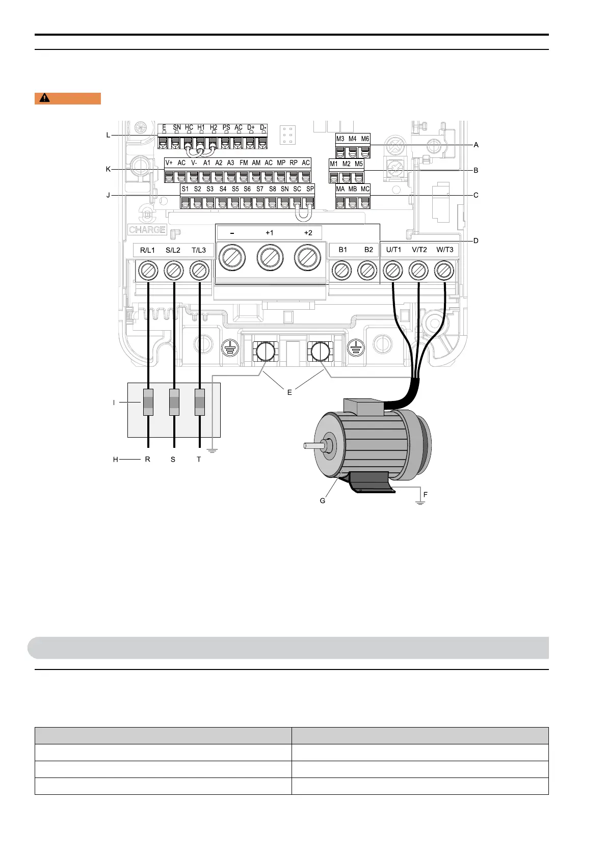
◆ Wiring the Main Circuit and Motor
Refer to Figure 10.3 for a view of the drive with line and load wiring.
WARNING
Electrical Shock Hazard. Do not connect terminals R/L1, S/L2, T/L3, U/T1, V/T2, W/T3, -, +1, +2, +3, B1, or
B2 to the ground terminal. Failure to obey can cause death, serious injury, or damage to equipment.
A - Terminal block (TB2-3)
B - Terminal block (TB2-2)
C - Terminal block (TB2-1)
D - DC bus voltage terminals
(configuration changes by drive
model)
E - Drive ground terminals
F - Motor case ground
G - Three-phase motor
H - Three-phase power supply
I - Fuses and RCD
J - Terminal block (TB1)
K - Terminal block (TB3)
L - Terminal block (TB4)
Figure 10.3 Wiring the Line and Load
11 Drive Start-Up
◆ Setup Wizard
Locate and record the following information before starting the drive. Refer to the drive and motor nameplates for
details.
Item Value
Motor Rated Power kW
Motor Rated Voltage V
Motor Rated Current A

 Loading...


