u
Terminal Configuration
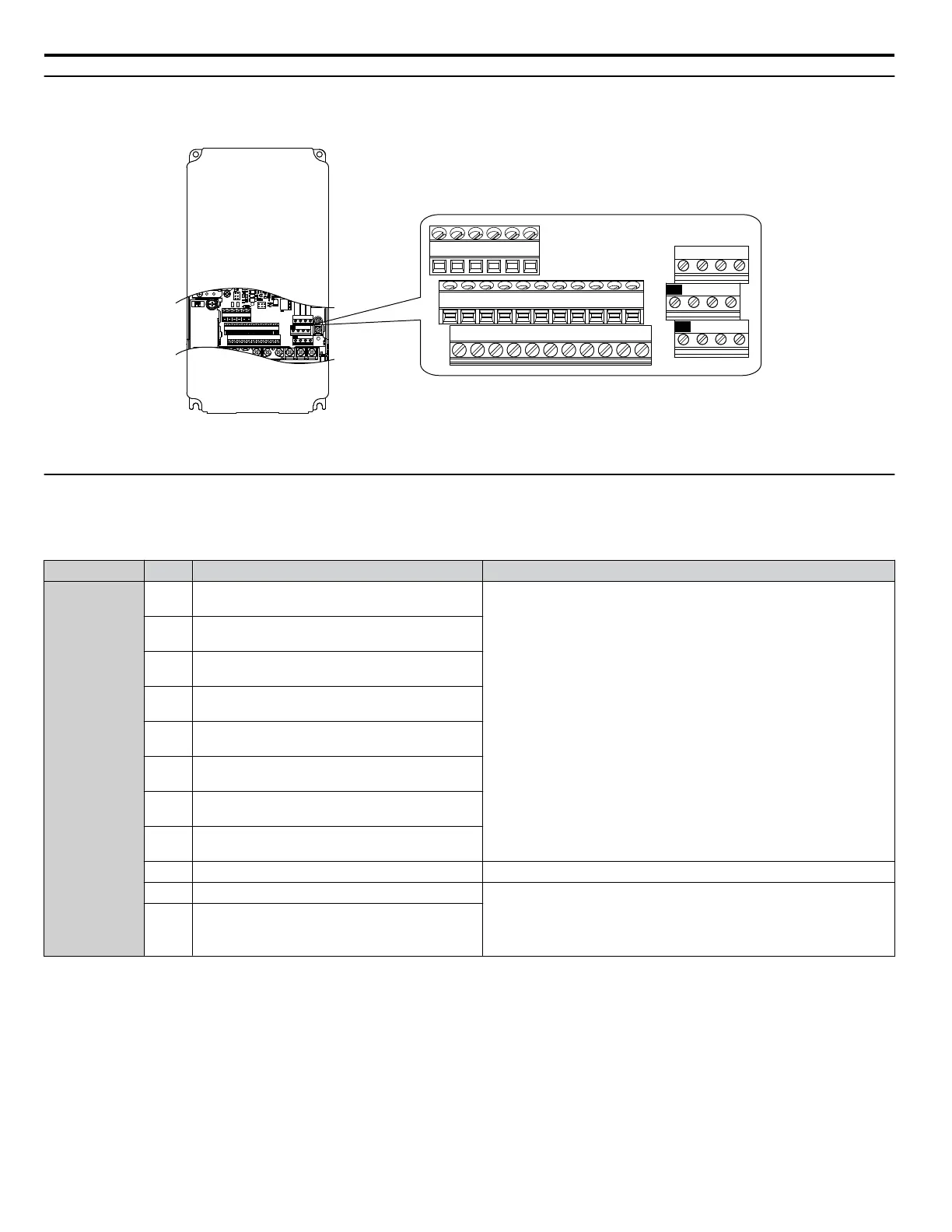
The control circuit terminals are arranged as shown in Figure i.12.
E(G)
IG R+ R- S+ S-
S1 S2 S3 S4 S5 S6 S7 S8 SN SC SP
V+ AC A1 A2 A3 FM AM AC 24VRP AC
M1 M2 M3 M4
MD ME MF
MA MB MC
E(G)
IG R+ R- S+ S-
S1 S2 S3 S4 S5 S6 S7 S8 SN SC SP
V+ AC A1 A2 A3 FM AM AC 24VRP AC
M1 M2 M3 M4
MD ME MF
MA MB MC
Figure i.12 Control Circuit Terminal Arrangement
u
Control Circuit Input Terminals
Table i.9 lists the input terminals on the drive. Text in parenthesis indicates the default setting for each multi-function input.
Table i.9 Control Circuit Input Terminals
Type No. Terminal Name (Function) Function (Signal Level) Default Setting
Multi-Function
Digital Inputs
S1
Multi-function input 1
(Closed: Forward run, Open: Stop)
• Photocoupler
• 24 Vdc, 8 mA
• Refer to Sinking/Sourcing Mode for Digital Inputs on page 41.
S2
Multi-function input 2
(Closed: Reverse run, Open: Stop)
S3
Multi-function input 3
(External fault, N.O.)
S4
Multi-function input 4
(Fault reset)
S5
Multi-function input 5
(Multi-step speed reference 1)
S6
Multi-function input 6
(Multi-step speed reference 2)
S7
Multi-function input 7
(Jog reference)
S8
Multi-function input 8
(Baseblock command (N.O.))
SC Multi-function input common Multi-function input common
SP Digital input power supply +24 Vdc 24 Vdc power supply for digital inputs, 150 mA max
NOTICE:
Do not jumper or short terminals SP and SN. Failure to
comply will damage the drive.
SN
Digital input power supply 0 V
24 V transducer power supply 0 V
i.3 Electrical Installation Safety
36
YASKAWA ELECTRIC TOEP YAIP1U 03B YASKAWA AC Drive – P1000 Safety Precautions

 Loading...


