n
Serial Communication Terminals
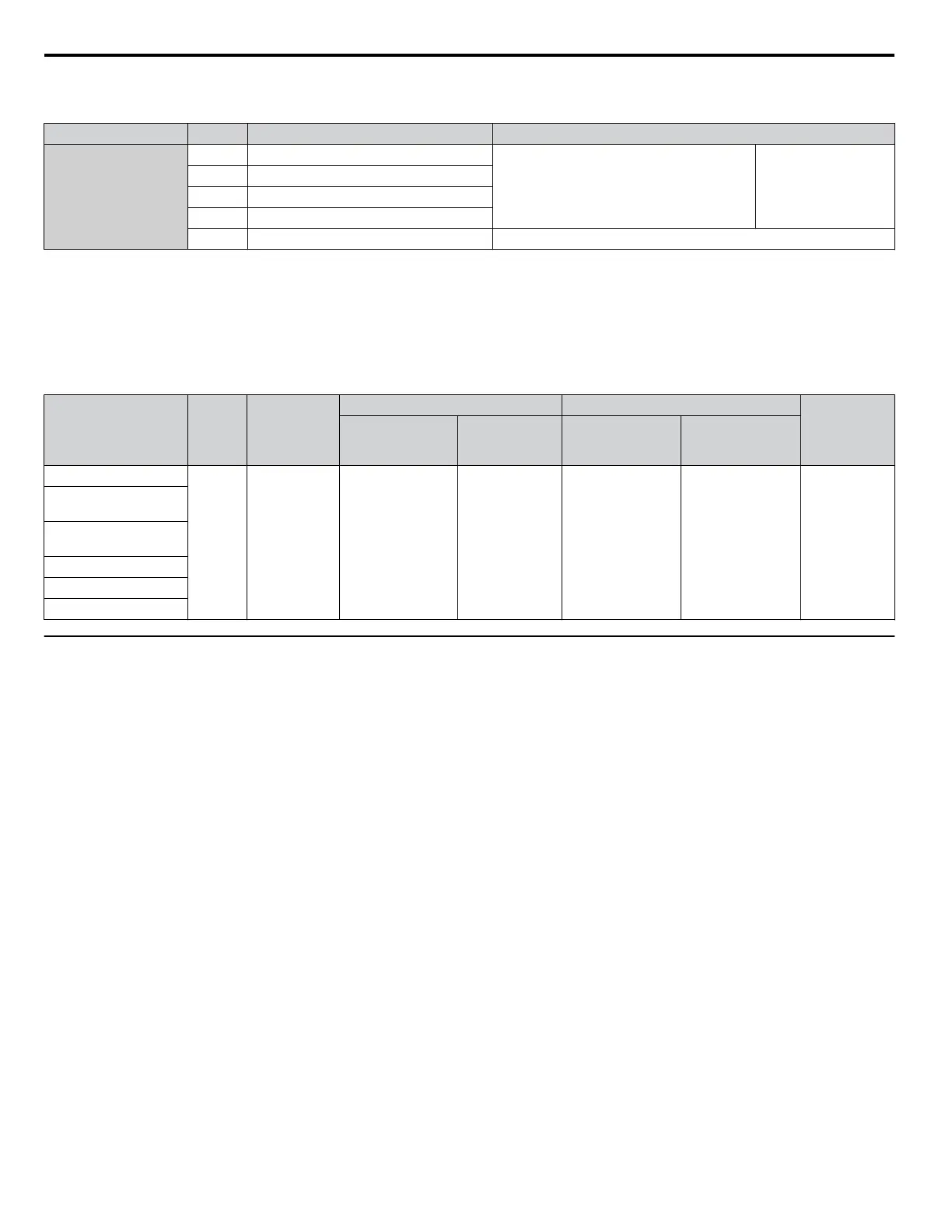
Table i.11 Control Circuit Terminals: Serial Communications
Type No. Signal Name Function (Signal Level)
MEMOBUS/Modbus
Communication
<1>
R+ Communications input (+)
MEMOBUS/Modbus communication: Use an
RS-422 or RS-485 cable to connect the drive.
RS-422/RS-485
MEMOBUS/Modbus
communication
protocol
115.2 kbps (max.)
R- Communications input (-)
S+ Communications output (+)
S- Communications output (-)
IG Shield ground 0 V
<1> Enable the termination resistor in the last drive in a MEMOBUS/Modbus network by setting DIP switch S2 to the ON position. Refer to the manual
section on Control I/O Connections for more information.
n
Control Circuit Wire Size and Torque Specifications
Select appropriate wire type and gauges from Table i.12. For simpler and more reliable wiring, use crimp ferrules on the wire
ends. Refer to the Technical Manual on the CD-ROM packaged with the drive for ferrule terminal types and sizes.
Table i.12 Wire Gauges
Terminal
Screw
Size
Tightening
Torque
N•m
(lb. in)
Bare Wire Terminal Ferrule-Type Terminal
Wire Type
Applicable
wire size
mm
2
(AWG)
Recomm.
wire size
mm
2
(AWG)
Applicable
wire size
mm
2
(AWG)
Recomm.
wire size
mm
2
(AWG)
S1-S8, SC, SN, SP
M3
0.5 to 0.6
(4.4 to 5.3)
Stranded wire:
0.2 to 1.0
(24 to 16)
Solid wire:
0.2 to 1.5
(24 to 16)
0.75 (18)
0.25 to 0.5
(24 to 20)
0.5 (20)
Shielded wire,
etc.
RP, V+, A1, A2, A3,
AC, 24 V
MA, MB, MC, MD, ME,
MF
M1-M4
FM, AM, AC
R+, R-, S+, S-, IG
u
Wiring the Control Circuit Terminal
This section describes the proper procedures and preparations for wiring the control terminals.
WARNING!
Electrical Shock Hazard. Do not remove covers or touch the circuit boards while the power is on. Failure to comply could result
in death or serious injury.
NOTICE:
Separate control circuit wiring from main circuit wiring (terminals R/L1, S/L2, T/L3, B1, B2, U/T1, V/T2, W/T3, ⊖, ⊕1, ⊕2) and
other high-power lines. Improper wiring practices could result in drive malfunction due to electrical interference.
NOTICE:
Separate wiring for digital output terminals MA, MB, MC, MD, ME, MF and M1 to M4 from wiring to other control circuit lines.
Improper wiring practices could result in drive or equipment malfunction or nuisance trips.
NOTICE:
Use a class 2 power supply when connecting to the control terminals. Improper application of peripheral devices could result in
drive performance degradation due to improper power supply. Refer to NEC Article 725 Class 1, Class 2, and Class 3 Remote-Control,
Signaling, and Power Limited Circuits for requirements concerning class 2 power supplies.
NOTICE:
Insulate shields with tape or shrink tubing to prevent contact with other signal lines and equipment. Improper wiring practices could
result in drive or equipment malfunction due to short circuit.
NOTICE:
Connect the shield of shielded cable to the appropriate ground terminal. Improper equipment grounding could result in drive or
equipment malfunction or nuisance trips.
NOTICE:
Do not tighten screws beyond the specified tightening torque. Failure to comply may result in erroneous operation, damage to the
terminal block, or cause a fire.
NOTICE:
Use shielded twisted-pair cables as indicated to prevent operating faults. Improper wiring practices could result in drive or
equipment malfunction due to electrical interference.
Wire the control circuit only after terminals have been properly grounded and main circuit wiring is complete. Refer to
Terminal Board Wiring Guide on page 39 for details. Prepare the ends of the control circuit wiring as shown in Figure i.
16. Refer to Wire Gauges on page 38.
Connect control wires as shown in Figure i.14 and Figure i.15.
i.3 Electrical Installation Safety
38
YASKAWA ELECTRIC TOEP YAIP1U 03B YASKAWA AC Drive – P1000 Safety Precautions

 Loading...


