u
Auto-Tuning
Auto-Tuning automatically sets up the motor data relevant drive parameters. Two different modes are supported.
Table i.19 Types of Auto-Tuning for Induction Motors
Type Setting Application Conditions and Benefits
Stationary Auto-Tuning for
Line-to-Line Resistance
T1-01 = 2
• The drive is used in V/f Control and other Auto-Tuning selections are not possible.
• Perform when entering motor data manually while using motor cables longer than 50 m.
• Drive and motor capacities differ.
• Tunes the drive after the cable between the drive and motor has been replaced with a cable over
50 m long. Assumes Auto-Tuning has already been performed.
Rotational Auto-Tuning for
V/f Control
T1-01 = 3
• Recommended for applications using Speed Estimation Speed Search or using the Energy Saving
function in V/f Control.
• Assumes motor can rotate while Auto-Tuning is executed. Increases accuracy for certain functions
like torque compensation, slip compensation, Energy Saving, and Speed Search.
Table i.20 lists the data that must be entered for Auto-Tuning. Make sure this data is available before starting Auto-Tuning.
The necessary information is usually listed on the motor nameplate or in the motor test report provided by the motor
manufacturer.
Table i.20 Auto-Tuning Input Data
Input Value Input Parameter Unit
Tuning Type (T1-01)
2
Line-to-Line Resistance
3
Rotational for V/f Control
Motor rated power T1-02 kW YES YES
Motor rated voltage T1-03 Vac – YES
Motor rated current T1-04 A YES YES
Motor rated frequency T1-05 Hz – YES
Number of motor poles T1-06 - – YES
Motor rated Speed T1-07 r/min – YES
Motor iron loss T1-11 W – YES
WARNING!
Electrical Shock Hazard. High voltage will be supplied to the motor when Stationary Auto-Tuning is performed even with the
motor stopped, which could result in death or serious injury. Do not touch the motor until Auto-Tuning has been completed.
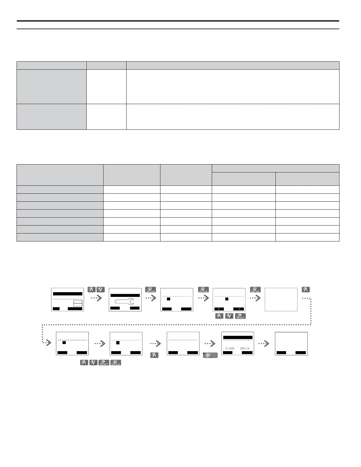
For Auto-Tuning enter the Auto-Tuning menu and perform the steps shown in the figure below. The number of name plate
data to be entered depends on the selected type of Auto-Tuning. This example shows Rotational Auto-Tuning.
- MODE -
End
Tune Successful
DRV
FWD RESET
Enter the Auto-
Tuning Mode
Select the tuning
method
Set up all
nameplate data
The tuning start
display appear s
During the tuning the
display flashes
After successful tuning
“End” is displayed
Drive mode
display
- A.TUNE -
T1-01= 2
2
Term Resistance
PRG
Entry Accepted
Tuning Mode Sel
FWD
- A.TUNE -
T1-01= 2
2
Term Resistance
PRG
Tuning Mode Sel
ESC FWD DATA
- MODE -
U1-01= 0.00Hz
U1-02= 0.00Hz
U1-03= 0.00A
DRV
FREF (OPR)
Rdy
JOG FWD FWD/REV
LSEQ
LREF
HELP
- MODE - PRG
Auto-Tuning
DATA
AUTO
FWD
“2”
- A.TUNE -
T1-07= 1450RPM
(0 ~ 24000)
PRG
Rated Speed
ESC FWD DATA
“1750RPM”
- A.TUNE -
T1-02= X.XXkW
(0.00 ~ 650.00)
PRG
Mtr Rated Power
ESC FWD DATA
“X.XXkW”
- A.TUNE -
0.00 Hz/ 0.00A
Tuning Ready ?
DRV
Auto-Tuning
ESC FWD
Press RUN key
- A.TUNE -
X.XX Hz/ X.XXA
DRV
Tune Proceeding
FWD
RUN
When Auto-Tuning cannot be performed, set up the maximum frequency and voltage in the E1-oo parameters and enter the
motor data manually into the E2-oo parameters.
i.5 Start Up
48
YASKAWA ELECTRIC TOEP YAIP1U 03B YASKAWA AC Drive – P1000 Safety Precautions

 Loading...


