5 Installation Procedure
YASKAWA ELECTRIC TOBP C730600 75B YASKAWA AC Drive Option PG-B3 Installation Manual 31
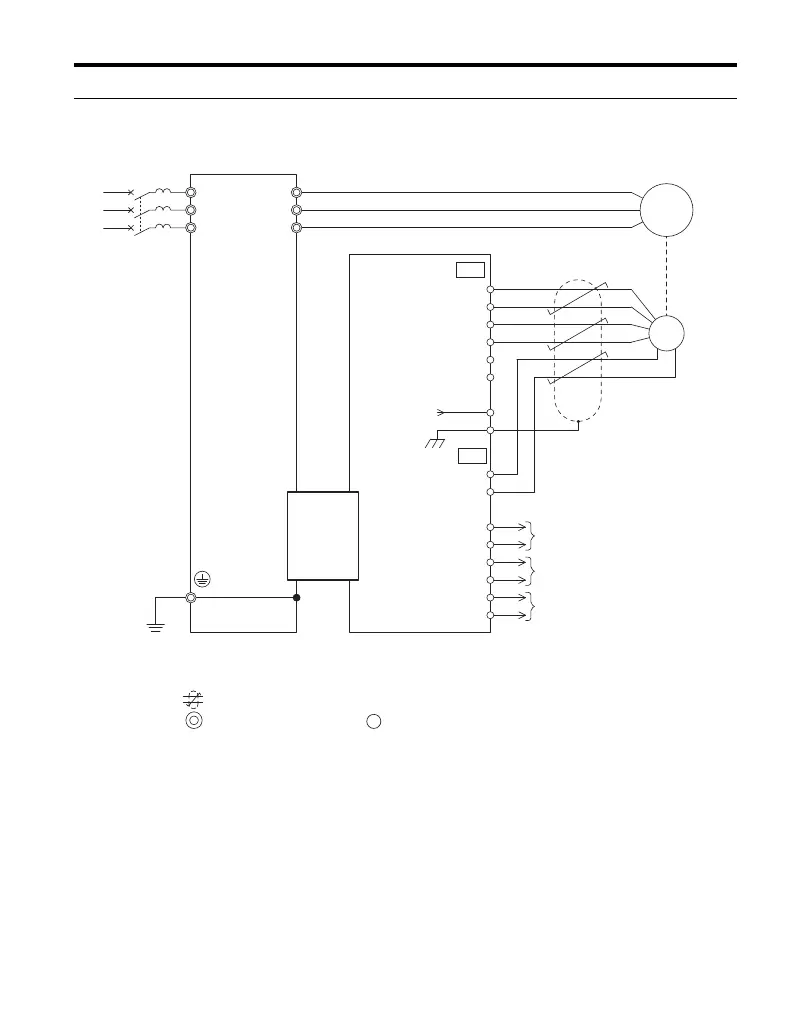
u Connection Diagram
Figure 21 PG-B3 Option and Encoder Connection Diagram
<1> Ground the shield on the PG encoder side and the drive side. Remove the shield ground from one end of the signal
line or remove the shield ground connection on both ends if electrical interference problems arise in the PG
encoder signal.
<2> Connect one of the included ground wires between the option FE terminal and the drive ground terminal
connected to earth ground for 1000-Series installation.
Fasten the option FE terminal in the ground plate using one of the included screws for GA700, CR700, and CH700
installation.
<3> Yaskawa recommends using shielded lines or shielded twisted-pair lines.
Shielded twisted-pair line
Main circuit terminal
Control circuit terminal
M
A+
A
B
Z
B+
Z+
AO
IG
BO
IG
ZO
IG
FE <2>
IP
IG
TB1
SD
TB2
NC
CN5
PGB3
Option
U/T1
V/T2
W/T3
R/L1
S/L2
T/L3
FE <2>
Drive
A pulse monitor signal
B pulse monitor signal
Z pulse monitor signal
PG
<1>
3
4
5
6
E
1
2
<3>
TOBP_C730600_75B_1_0_E.book 31 ページ 2017年2月17日 金曜日 午後3時2分