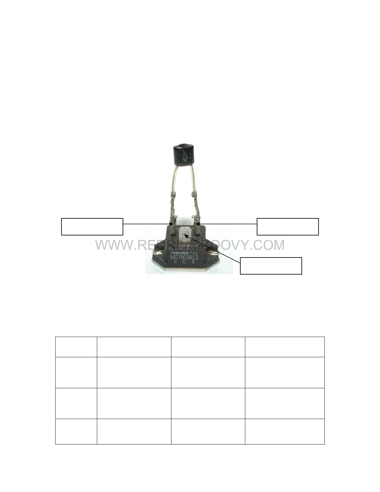
16. Regen Transistor
When the servomotor is turned off, there is still a voltage present across
the main bus of the servo. The regen transistor acts as a switch with
closes when the servo is turned off to allow this voltage through to the
Y3 and Y4 terminals. Here it is dissipated across resistors 1 and 2. When
checking the regen transistor, you are making sure it hasn’t been shorted
across the emitter and collector.
Base
Collector
Emitter
17.
Regen Transistor Check
Test Equipment – Digital Multimeter
Step #
Multimeter
Positive Lead
Multimeter
Negative Lead
Expected Reading
(Diode Check)
1 Base Collector
Approximately 0.5
Volts.
2 Emitter Collector
Approximately 0.4
Volts.
3 Emitter Base
Approximately 0.7
Volts.
 Loading...


