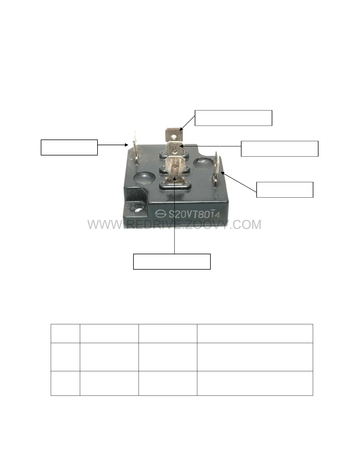
18. Diode Bridge #1
The diode bridge #1 is a component in the braking circuit. When the
servomotor is turned off, the continued spinning of the motor generates a
voltage across U, V, and W. The diode bridge directs the current from
this voltage to the braking resistor to be dissipated. This results in a
smooth braking of the motor.
Module Terminal 1
(+)
Module Terminal 2
(-)
Module Terminal 3
19. Diode bridge #1 Check
Test Equipment – Digital Multimeter
Step #
Multimeter
Positive Lead
Multimeter
Negative Lead
Expected Reading (Diode
Check)
1
Negative
module
terminal
Module
terminal 1, 2, 3
Approximately 0.5 Volts must be
consistent with each other.
2
Module
terminal 1, 2, 3
Positive module
terminal
Approximately 0.5 Volts must be
consistent with each other.

 Loading...


