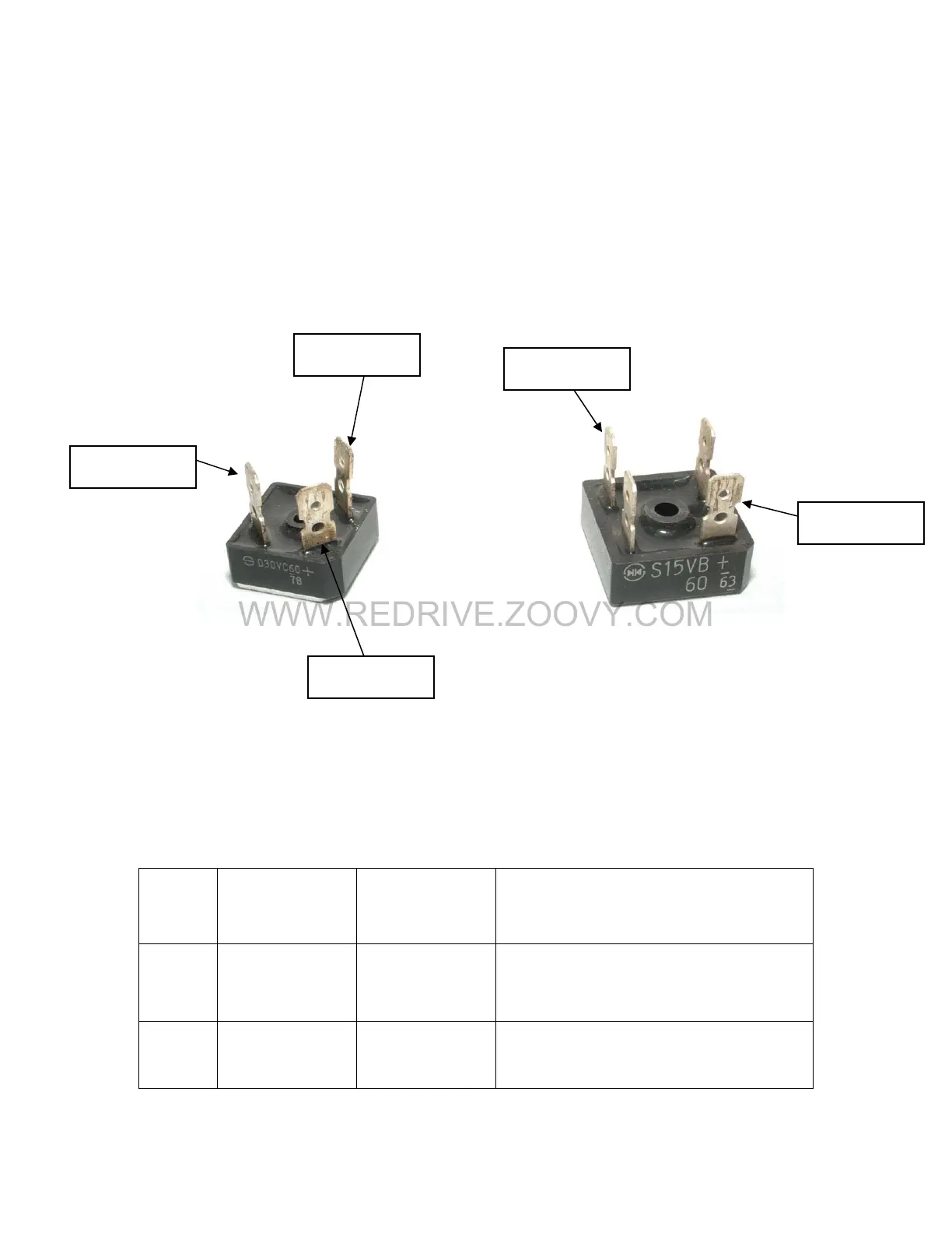
20. Diode Bridge #2
Diode bridges are used to rectify voltage wave patterns. In this case, the
input voltage is the three phase AC voltage RST. In order for this voltage
to be useful to the PTM, it must first be converted to a DC voltage
pattern. The diode bridge #2 further rectifies the voltage out of the
Thyristor into DC voltage, which is then sent to the power transistor
module.
2
2, 3
3
1
1
21.
Diode Bridge #2 Check
Test Equipment – Digital Multimeter
Step #
Multimeter
Positive
Lead
Multimeter
Negative
Lead
Expected Reading (Diode
Check)
1 Terminal (2) Terminal (1)
Approximately 0.5 Volts must be
consistent with terminal (2).
2 Terminal (3) Terminal (1)
Approximately 0.5 Volts must be
consistent with terminal (3).

 Loading...


