4-14
* 4. For an Inverter motor or vector motor, the voltage and frequency may be lower than for a general-purpose motor. Always confirm setting on the name-
plate or in test reports. Also, if you know the no-load values, set the no-load voltage in T1-03 and the no-load frequency in T1-05 to obtain better accu-
racy.
* 5. Stable vector control will be possible when the setting is between 50% and 100% of Inverter rating.
* 6. The factory setting depends on the Inverter capacity. The values for a 200 V Class Inverter for 0.4 kW are given.
* 7. When C6-01=0, the upper limit is 150.00.
* 8. The setting range depends on the Inverter capacity. The value for a 200 V Class Inverter for 0.4 kW is given.
* 9. Set T1-02 and T1-04 when 2 is set for T1-01. Only set value 2 is possible for V/f control or V/f control with PG.
* 10.The setting range is from 10% to 200% of the Inverter rated output current. The value for a 200 V Class Inverter for 0.4 kW is given.
* 11.When C6-01=1, the upper limit is 400.00.
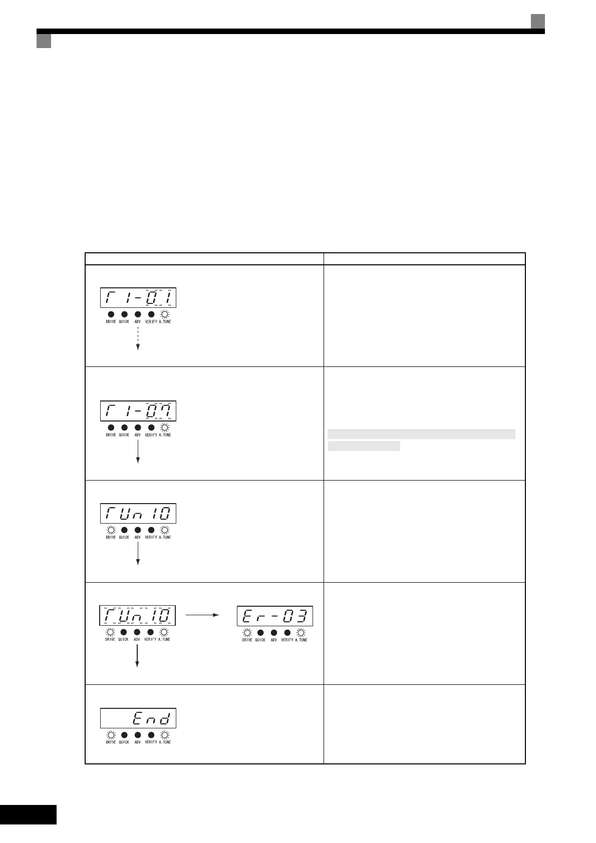
Digital Operator Displays during Autotuning
The following displays will appear on the Digital Operator during autotuning.
Table 4.4 Digital Operator Displays during Autotuning
Digital Operator Display Description
Autotuning mode selection: T1-01
Using the same procedures as for the programming
modes check and set the T1 constants according to
information on the previous page.
Be sure that T1-01 (Autotuning Mode Selection) is set
correctly and check safety around the motor and
machine.
Motor base speed: T1-07
(For rotational autotuning)
The autotuning start display will appear when all set-
tings through T1-07 have been completed. The
A.TUNE and DRIVE indicators will be lit.
Autotuning started: TUn10
Autotuning will start when the RUN Key is pressed
from the autotuning start display.
The digit second from the right in TUn
is the
Motor 1/2 Selection (T1-00) and the right digit is the
Autotuning Mode Selection (T1-01).
Autotuning Stop Command input
If the STOP Key is pressed or a measurement error
occurs during autotuning, and error message will be
display and autotuning will be stopped.
Refer to Errors during Autotuning on page 7-15.
Autotuning completed
END will be displayed after approximately 1 to 2 min-
utes, indicating that autotuning has been completed.
If using stationary autotuning 2, all settings through
T1-09 are to be set.

 Loading...


