Wiring Main Circuit Terminals
2-13
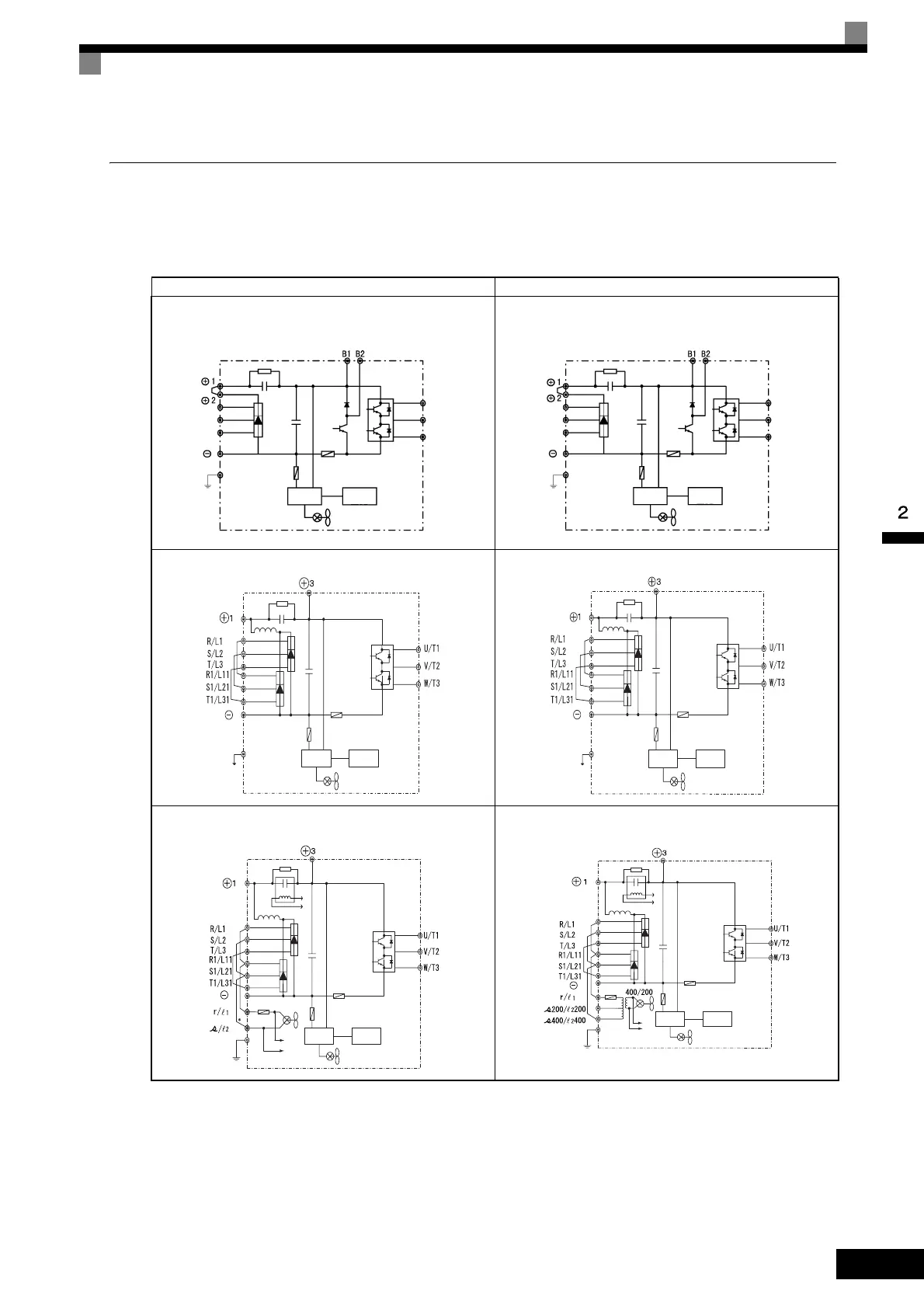
Main Circuit Configurations
The main circuit configurations of the Inverter are shown in Fig 2.5.
Table 2.5 Inverter Main Circuit Configurations
Note Consult your Yaskawa representative before using 12-phase rectification.
* These terminals are wired before shipment. When using DC power for the main circuit power supply, remove the wires between R-r/l
1
and S-s/l
2
, then, for
200 V Class Inverters, input 200 VAC to r/l
1
- s/l
2
, or, for 400 V Class Inverters, input either 200 VAC to r/l
1
- s200/l
2
200 or 400 VAC to r/l
1
- s400/l
2
400.
200 V Class 400 V Class
CIMR-F7A20P4 to 2018
Power
supply
Control
circuits
R/L1
S/L2
T/L3
U/T1
V/T2
W/T3
CIMR-F7A40P4 to 4018
Power
supply
Control
circuits
R/L1
S/L2
T/L3
U/T1
W/T3
V/T2
CIMR-F7A2022, 2030
Power
supply
Control
circuits
CIMR-F7A4022 to 4055
Power
supply
Control
circuits
a
Power
supply
Control
circuits
b
a
b
CIMR-F7A2037 to 2110
a
b
a
b
Power
supply
Control
circuits
CIMR-F7A4075 to 4300

 Loading...


