10-24
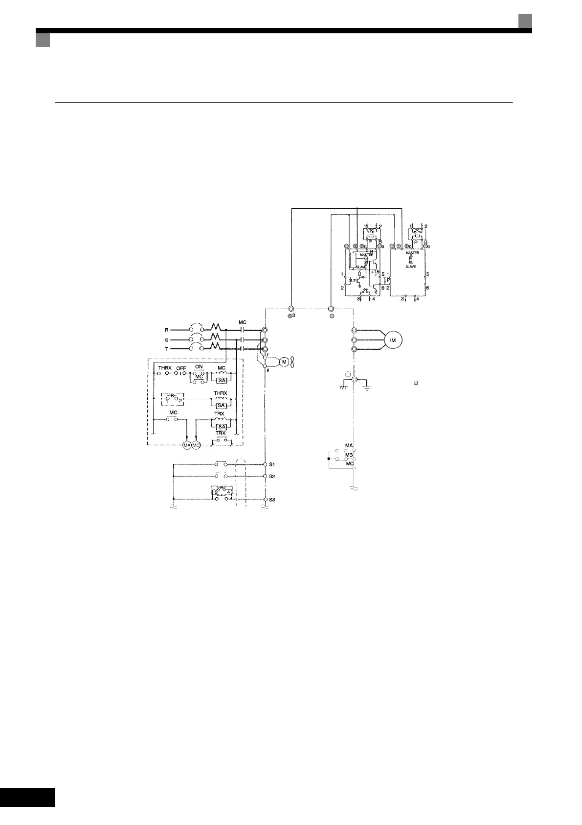
Using Braking Units in Parallel
This example shows wiring for using two Braking Units in parallel.
There are connectors for selecting whether each Braking Unit is to be a Master or Slave. Select “Master” for
the first Braking Unit only, and select “Slave” for all other Braking Units (i.e.) from the second Unit onwards.
Fig 10.11
3-phase power
200 to 220 V 50 Hz
200 to 230 V 60 Hz
Ground to 100
max.
Fault contact output
Forward Run Com-
mand (forward run
when ON)
Reverse Run Com-
mand (reverse run
when ON)
* Disable stall prevention during deceleration by setting L3-04 to Resistor Unit. The motor may not stop
within the deceleration time if this setting is not changed.
A sequence is required to turn OFF the
power supply for the thermal overload relay
trip contacts of the Braking Resistor Unit.
Inverter
Motor
R/L1
T/L3
S/L2
U/T1
V/T2
W/T3
Cooling fan
Braking Unit
MCCB
Thermal
protector
Overload relay trip contact
of Braking Resistor Unit
Thermal
protector
Braking
Resistor
Unit
Braking
Resistor
Unit
Thermal switch
Thermal switch
Level
detector
Fault contacts
Forward Run/Stop
Reverse Run/Stop
Braking Unit
External fault

 Loading...


