1-6
Component Names
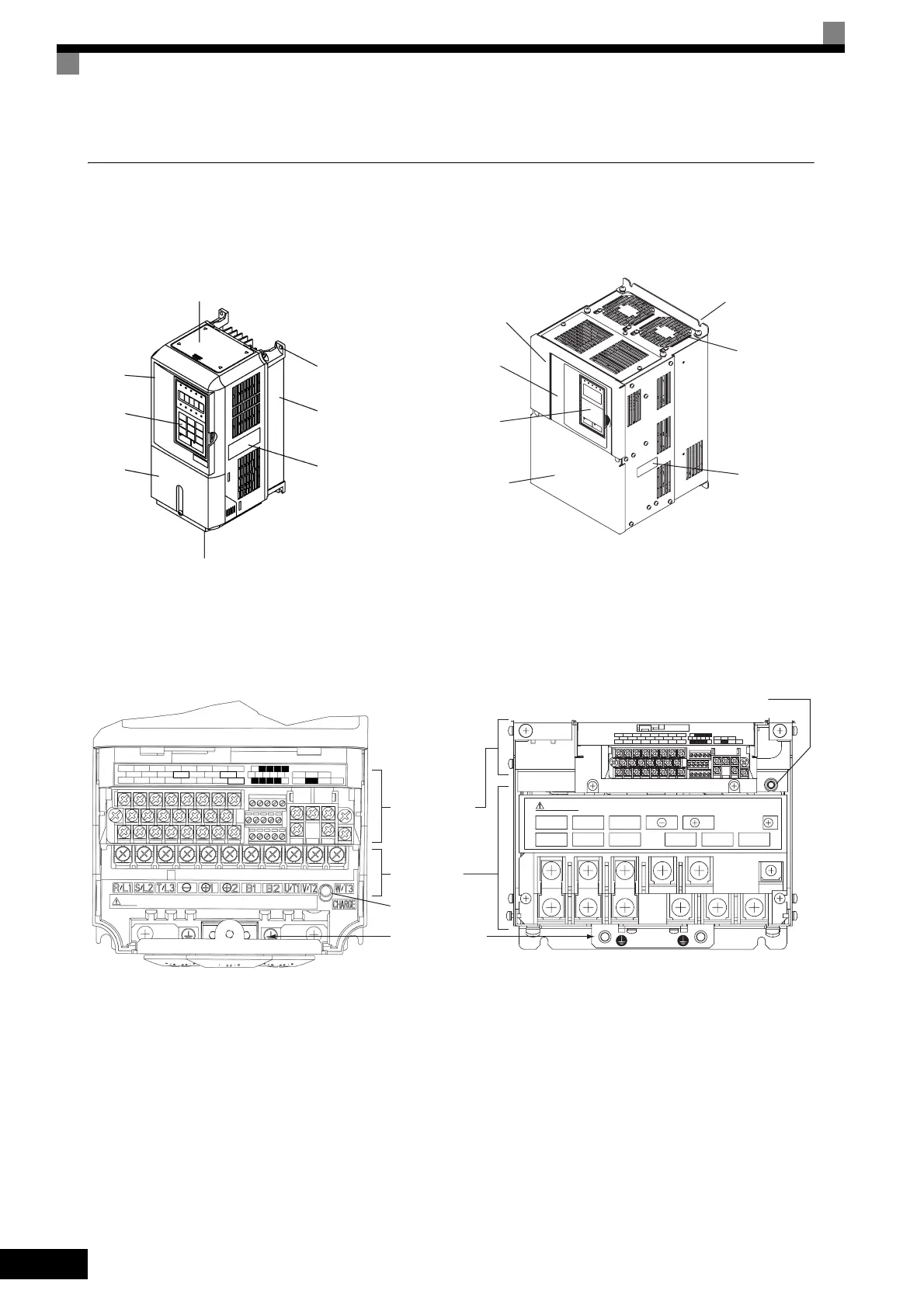
The external appearance and component names of the Inverter are shown in Fig 1.4. The Inverter with the ter-
minal cover removed is shown in Fig 1.5.
Fig 1.4 Inverter Appearance
Fig 1.5 Terminal Arrangement (Examples of Inverters with SPEC: E or later)
Inverter cover
Mounting
hole
Cooling
fan
Nameplate
Front cover
Digital
Operator
Terminal
cover
Top protective cover
Bottom protective cover
18.5 kW or Less 22 kW or More
Mounting hole
Front
cover
Digital
Operator
Terminal
cover
Diecast case
Nameplate
Control circuit
terminals
Charge indicator
R1/L11
R1/L1 S/L2 T/L3 U/T1 V/T2
1
W/T3
S1/L21 T1/L21
Main circuit
terminals
Charge indicator
Ground terminal
E (G) FM AC AM
SC A1 A2 +V AC
P1 P2 PC
S1 S2 S3 S4
S5
S6 S7
SC
MA
M1
MB MC
M2
E (G)
MP
RP R+ R- S+ S-
IG
A3
S8
-V
18.5 kW or Less 22 kW or More
3

 Loading...


