Wiring Control Circuit Terminals
2-23
Wiring Control Circuit Terminals
Wire Sizes and Closed-loop Connectors
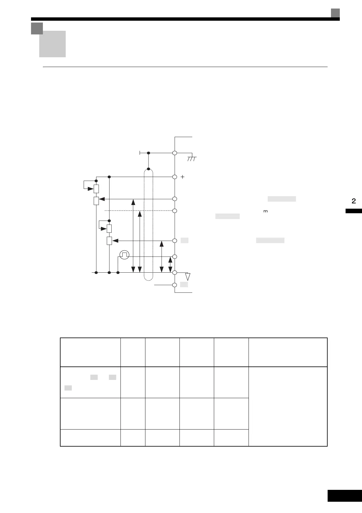
For remote operation using analog signals, keep the control line length between the Digital Operator or opera-
tion signals and the Inverter to 50 m or less, and separate the lines from high-power lines (main circuits or
relay sequence circuits) to reduce induction from peripheral devices.
When setting frequencies from an external frequency setter (and not from a Digital Operator), use shielded
twisted-pair wires and ground the shield to terminal E (G), as shown in the following diagram.
Fig 2.17
Terminal numbers and wire sizes are shown in Table 2.9.
* 1. Use shielded twisted-pair cables to input an external frequency reference.
*2.Refer to Table 2.3 Close-loop Connector Sizes for suitable closed-loop crimp terminal sizes for the wires.
* 3. We recommend using straight solderless terminal on signal lines to simplify wiring and improve reliability.
Table 2.9 Terminal Numbers and Wire Sizes (Same for all Models)
Terminals
Termi-
nal
Screws
Tightening
Torque
(N•m)
Possible
Wire Sizes
mm
2
(AWG)
Recom-
mended
Wire Size
mm
2
(AWG)
Wire Type
FM, AC, AM, P1, P2, PC,
SC, A1, A2, , +V, ,
S1, S2, S3, S4, S5, S6, S7,
, MA, MB, MC, M1,
M2
M3.5 0.8 to 1.0
0.5 to 2
*2
(20 to 14)
0.75
(18)
• Shielded, twisted-pair wire
*1
• Shielded, polyethylene-cov-
ered, vinyl sheath cable
(KPEV-S by Hitachi Electrical
Wire or equivalent)
MP, RP, R+, R-, S+, S-,
IG
Phoenix
type
0.5 to 0.6
Single wire
*3
:
0.14 to 2.5
Stranded wire:
0.14 to 1.5
(26 to 14)
0.75
(18)
E (G) M3.5 0.8 to 1.0
0.5 to 2
*2
(20 to 14)
1.25
(12)
P
P
P
P
E(G)
Shield terminal
V Speed setting power
supply +15 V 20 mA
A1 Master speed reference 0 to 10 V (-10 to 10 V)
A2 Master speed reference 4 to 20
A
(0 to 10 V, -10 to 10 V)
A3 Auxiliary reference 0 to 10 V (-10 to 10 V)
RP Pulse train input 32 kHz max.
AC Analog common
2kΩ
2kΩ
2kΩ
2kΩ
-V Speed setting power supply -15 V 20 mA
A3 -V
S8

 Loading...


