2-22
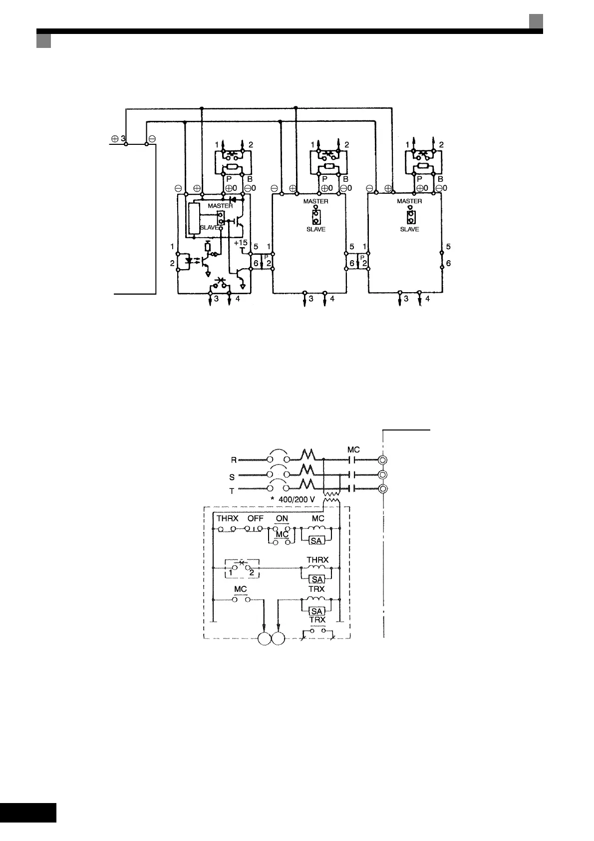
Fig 2.15 Connecting Braking Units in Parallel
Breaking Unit Application Precautions
When using a Braking Resistor Unit, create a sequence to detect overheating of the braking resistor and turn
OFF the power supply to the Inverter.
Fig 2.16 Power Shutoff Sequence
Inverter
Braking resistor overheat-
ing contacts (Thermal pro-
tector contacts)
Braking resistor overheat-
ing contacts (Thermal pro-
tector contacts)
Braking resistor overheat-
ing contacts (Thermal pro-
tector contacts)
Braking
Resistor
Unit
Braking
Resistor
Unit
Braking
Resistor
Unit
Level
detector
Braking Unit #2 Braking Unit #3
Braking Unit #1
Cooling fin overheating con-
tacts (thermostat contacts)
Cooling fin overheating con-
tacts (thermostatic contacts)
Cooling fin overheating con-
tacts (thermostatic contacts)
Inverter
Three-phase power:
200 to 240 V, 50/60 Hz or
380 to 480 V, 50/60 Hz
MCCB
Overload relay trip contact
of Braking Resistor Unit
Fault contacts
* Use a transformer with 200 and 400 V outputs for the power 400 V Inverter.
R/L1
S/L2
T/L3
MC
MA

 Loading...


