Wiring Main Circuit Terminals
2-21
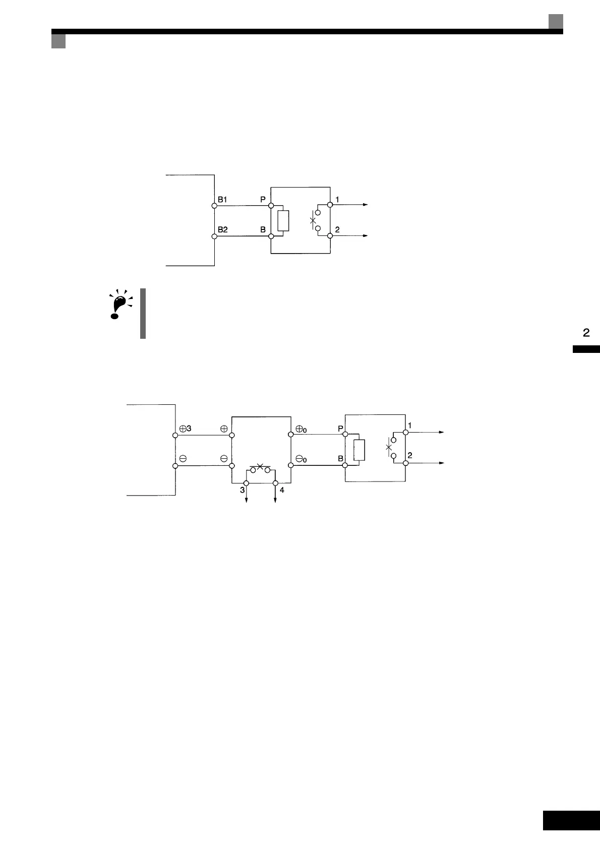
To prevent the Unit from overheating, design the sequence to turn OFF the power supply for the thermal over-
load relay trip contacts of the Unit as shown in Fig 2.14.
200 V and 400 V Class Inverters with 0.4 to 18.5 kW Output
200 V and 400 V Class Inverters with 22 kW or higher Output
Fig 2.14 Connecting the Braking Resistor Unit and Braking Unit
Connecting Braking Units in Parallel
When connecting two or more Braking Units in parallel, use the wiring and connectors shown in Fig 2.15.
There are connectors for selecting whether each Braking Unit is to be a Master or Slave. Select “Master” for
the first Braking Unit only, and select “Slave” for all other Braking Units (i.e., from the second Unit onwards).
IMPORTANT
When connecting an separately-installed type Braking Resistor Unit (model CDBR), connect the B1 terminal
of the Inverter to the + terminal of the Braking Resistor Unit and connect the − terminal of the Inverter to the −
terminal of the Braking Resistor Unit. The B2 terminal is not used in this case.
Inverter
LKEB Braking
Resistor Unit
Thermal overload
relay trip contact
Inverter
LKEB Braking
Resistor Unit
Thermal overload
relay trip contact
CDBR Braking
Unit
Thermal protector
trip contact

 Loading...


