User Constant Tables
5-19
* 1. The factory setting is 1.0 when using flux vector control.
* 2. The factory setting is 2.00 s when Inverter capacity is 55 kW min.
The factory setting will change when the control method is changed. The open-loop vector factory setting is given.
* 3. By setting E2-11 (Motor rated output) the appropriate value will be set.
* 4. The factory setting depends on the Inverter capacity. The value for a 200 V Class Inverter of 0.4 kW is given.
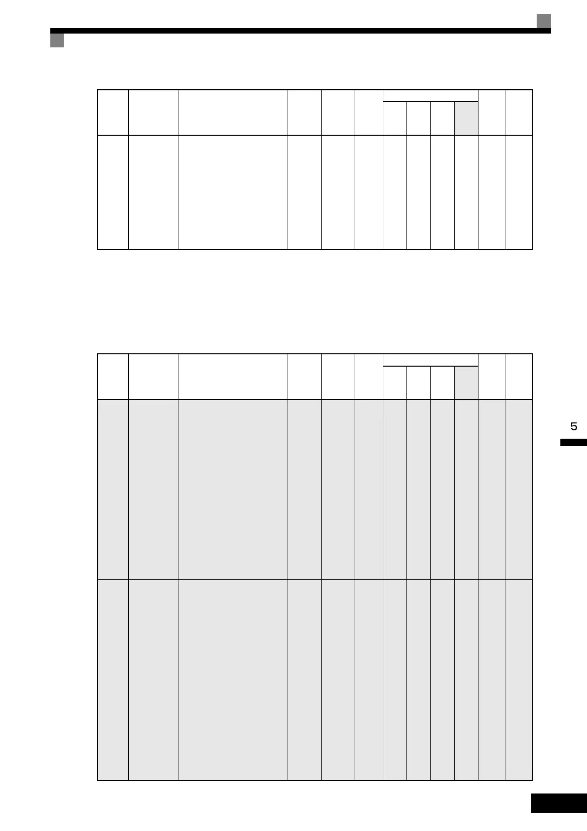
Zero-Servo: b9
User constants for zero-servo functions are shown in the following table.
b8-06
Search
operation
voltage lim-
iter
Set the limit value of the
voltage control range during
search operation.
Perform search operation to
optimize operations using
minute variations in voltage
using energy-saving control.
Set to 0 to disable the search
operation. 100% is the motor
base voltage.
0 to
100
0% No A A No No 1D1H 6-117
Con-
stant
Number
Name Description
Setting
Range
Factory
Setting
Change
during
Opera-
tion
Control Methods
MEMO
BUS
Regis-
ter
Page
V/f
V/f
with
PG
Open
Loop
Vec-
tor
Flux
Vec-
tor
b9-01
Zero-servo
gain
Adjust the strength of the
zero-servo lock.
Enabled when the “zero-
servo command” is set for
the multi-function input.
When the zero-servo com-
mand has been input and the
frequency reference drop
below excitation level (b2-
01), a position control loop
is created and the motor
stops. Increasing the zero-
servo gain in turn increases
the strength of the lock.
Increasing it by too much
will cause oscillation.
0 to
100
5 No No No No A 1DAH 6-144
b9-02
Zero-servo
completion
width
Sets the output width of the
zero-servo completion sig-
nal.
Enabled when the “zero-
servo completion (end)” is
set for a multi-function
input. The zero-servo com-
pletion signal is ON when
the current position is within
the range (the zero-servo
start position± zero-servo
completion width.)
Set the allowable position
displacement from the zero-
servo start position to 4
times the pulse rate of the
PG (pulse generator,
encoder) in use.
0 to
16383
10 No No No No A 1DBH 6-144
Con-
stant
Number
Name Description
Setting
Range
Factory
Setting
Change
during
Opera-
tion
Control Methods
MEMO
BUS
Regis-
ter
Page
V/f
V/f
with
PG
Open
Loop
Vec-
tor
Flux
Vec-
tor

 Loading...


