5-84
Note Attach a Momentary Power Interruption Compensation Unit if compensation for power interruptions of up to 2.0 seconds is required for 200 V Class
Inverters with outputs of 0.4 to 11 kW.
* 1. The factory settings when VT is selected are given.
When CT is selected, the factory settings are as follows for Inverters of any capacity:
Carrier frequency selection: 1 (2.0 kHz)
Carrier frequency selection upper limit: 2.5 kHz
* 2. The setting of C6-02 changes the carrier frequency selection as follows:
0: Low-noise PWM, 1: 2.0 kHz, 2: 5.0 kHz, 3: 8.0 kHz, 4: 10.0 kHz, 5: 12.5 kHz, 6: 15.0 kHz
* 3. 95 for Inverter SPEC Type A.
* 4. When setting the carrier frequency of 200 V Class Inverters of 30 kW or more to a value larger than the factory setting, reduce the value of the Inverter
rated output current.
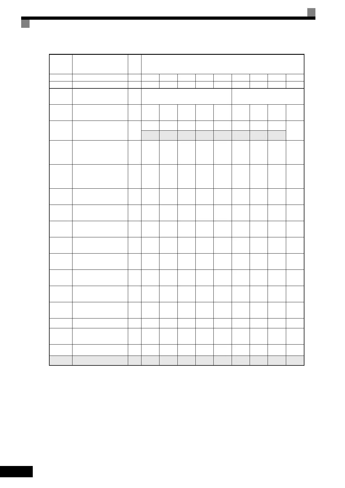
Con-
stant
Number
Name Unit Factory Setting
- Inverter Capacity kW 18.5 22 30 37 45 55 75 90 110
o2-04 kVA selection - 9 A B C D E F 10 11
b8-03
Energy-saving filter time
constant
s 0.50 (Open loop vector control) 2.00 (Open loop vector control)
b8-04
Energy-saving coeffi-
cient
-
57.87 51.79 46.27 38.16 35.78 31.35 23.10 20.65 18.12
C6-01 CT/VT selection -
11111111
1
0 0 0 0 0 0 0 0
C6-02
Carrier frequency selec-
tion (when VT is
selected)
*1 *4
-
6
*2
6
*2
4
*2
3
*2
3
*2
3
*2
2
*2
2
*2
1
*2
-
Carrier frequency selec-
tion upper limit (when
VT is selected)
*1
-666444441
E2-01
(E4-01)
Motor rated current A
65.8 77.2 105.0 131.0 160.0 190.0 260.0 260.0 260.0
E2-02
(E4-02)
Motor rated slip Hz 1.67 1.70 1.80 1.33 1.60 1.43 1.39 1.39 1.39
E2-03
(E4-03)
Motor no-load current A 15.7 18.5 21.9 38.2 44.0 45.6 72.0 72.0 72.0
E2-05
(E4-05)
Motor line-to-line resis-
tance
Ω
0.101 0.079 0.064 0.039 0.030 0.022 0.023 0.023 0.023
E2-06
(E4-06)
Motor leak inductance % 20.1 19.5 20.8 18.8 20.2 20.5 20.0 20.0 20.0
E2-10
Motor iron loss for
torque compensation
W
505 538 699 823 852 960 1200 1200 1200
L2-02
Momentary power loss
ridethru time
s 2.0 2.0 2.0 2.0 2.0 2.0 2.0 2.0 2.0
L2-03
Min. baseblock (BB)
time
s 1.0 1.0 1.1 1.1 1.2 1.2 1.3 1.5 1.7
L2-04 Voltage recovery time s 0.6 0.6 0.6 0.6 1.0 1.0 1.0 1.0 1.0
L2-08
Frequency reduction
gain at KEB start
°C959595959595959595
L8-02 Overheat pre-alarm level °C 100 90 90 95 100 105 110 100
110
*3
N5-02 Motor acceleration time s 0.317 0.355 0.323 0.320 0.387 0.317 0.533 0.592 0.646

 Loading...


