User Constant Tables
5-87
Note Attach a Momentary Power Interruption Compensation Unit if compensation for power interruptions of up to 2.0 seconds is required for 200 V Class
Inverters with outputs of 0.4 to 11 kW.
* 1. The factory settings when VT is selected are given.
When CT is selected, the factory settings are as follows for Inverters of any capacity:
Carrier frequency selection: 1 (2.0 kHz)
Carrier frequency selection upper limit: 2.5 kHz
* 2. The setting of C6-02 changes the carrier frequency selection as follows:
0: Low-noise PWM, 1: 2.0 kHz, 2: 5.0 kHz, 3: 8.0 kHz, 4: 10.0 kHz, 5: 12.5 kHz, 6: 15.0 kHz
* 3. When setting the carrier frequency of 400 V Class Inverters of 30 kW or more to a value larger than the factory setting, reduce the value of the Inverter
rated output current.
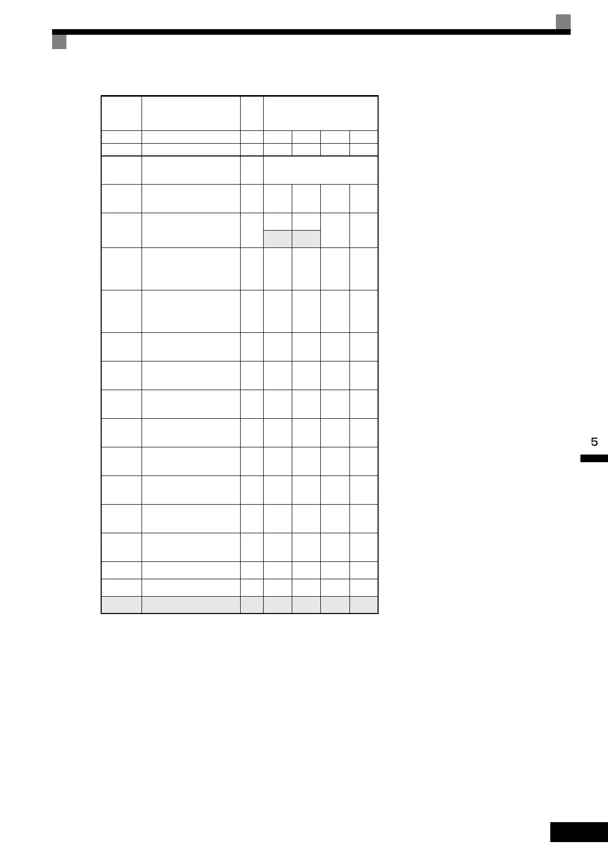
Con-
stant
Number
Name Unit Factory Setting
- Inverter Capacity kW 160 185 220 300
o2-04 kVA selection - 34 35 36 37
b8-03
Energy-saving filter time
constant
s
2.00 (Open loop vector con-
trol)
b8-04
Energy-saving coeffi-
cient
-
30.13 30.57 27.13 21.76
C6-01 CT/VT selection -
11
11
0 0
C6-02
Carrier frequency selec-
tion (when VT is
selected)
*1 *3
-
2
*2
2
*2
1
*2
1
*2
-
Carrier frequency selec-
tion upper limit (when
VT is selected)
*1
-4211
E2-01
(E4-01)
Motor rated current A
270.0 310.0 370.0 500.0
E2-02
(E4-02)
Motor rated slip Hz 1.35 1.30 1.30 1.25
E2-03
(E4-03)
Motor no-load current A
70.0 81.0 96.0 130.0
E2-05
(E4-05)
Motor line-to-line resis-
tance
Ω
0.029 0.025 0.020 0.014
E2-06
(E4-06)
Motor leak inductance % 20.0 20.0 20.0 20.0
E2-10
Motor iron loss for
torque compensation
W
2850 3200 3700 4700
L2-02
Momentary power loss
ridethru time
s 2.0 2.0 2.0 2.0
L2-03
Min. baseblock (BB)
time
s 1.8 1.9 2.0 2.1
L2-04 Voltage recovery time s 1.0 1.0 1.0 1.0
L8-02 Overheat pre-alarm level °C 108 95 100 108
N5-02 Motor acceleration time s 0.777 0.864 0.910 1.392

 Loading...


