Frequency Reference
6-11
Setting Precautions
Refer to the following to set step 1 to step 3 to analog inputs.
• Step 1
When setting terminal A1's analog input to step 1, set b1-01 to 1, and when setting d1-01 (Frequency Ref-
erence 1) to step 1, set b1-01 to 0.
• Step 2
When setting terminal A2's analog input to step 2, set H3-09 to 2 (aux-
iliary frequency reference 1). When setting d1-02 (Frequency Reference 2) to step 2, do not set H3-09
to 2.
•
When setting terminal A3's (or A2's) analog input to step 3, set H3-05 (H3-09 when A2 is used) to 3 (aux-
iliary frequency reference 2). When setting d1-03(Frequency Reference 3) to step 3, do not set H3-05 (H3-
09 when A2 is used) to 3.
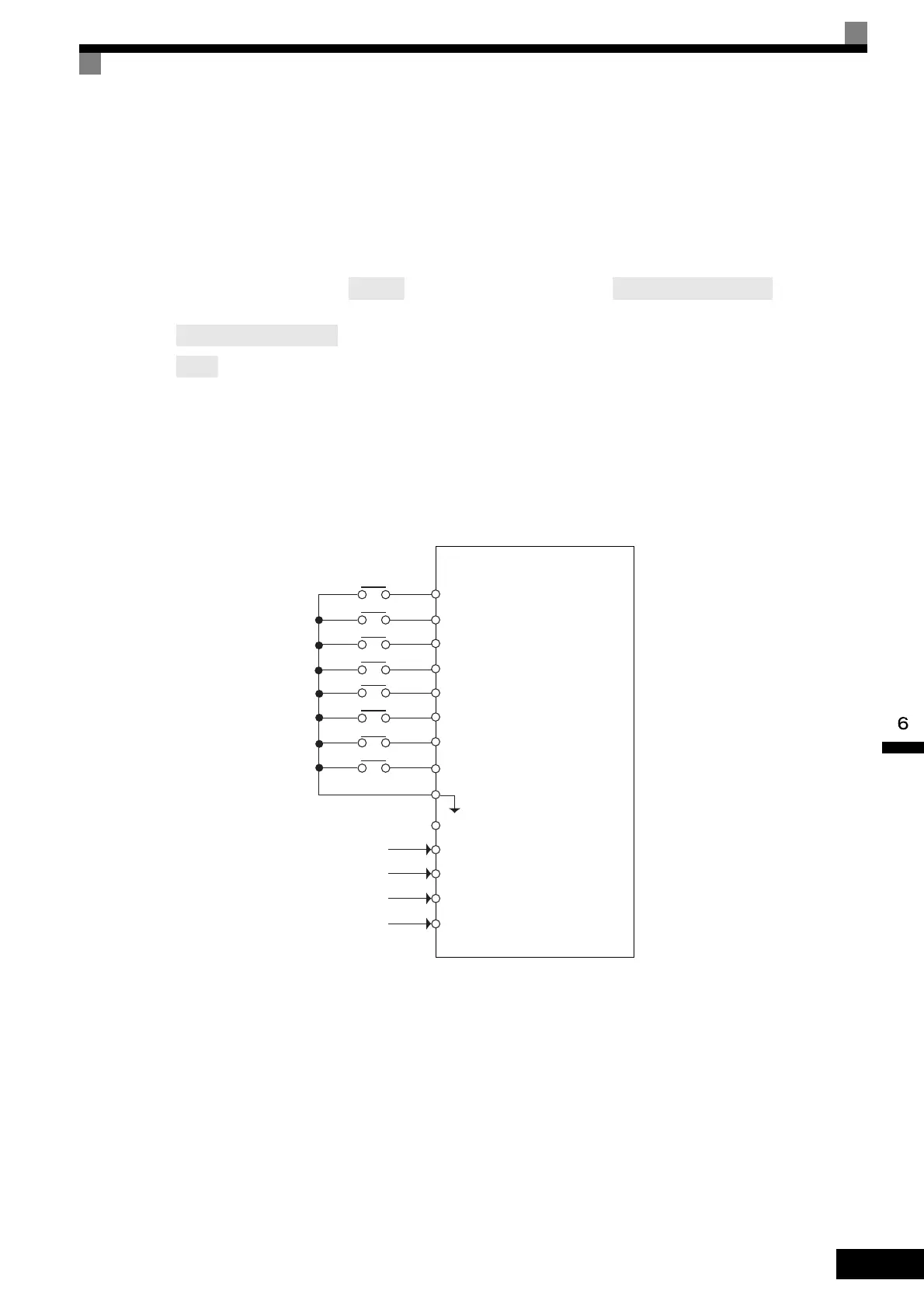
Connection Example and Time Chart
The following diagram shows a time chart and control circuit terminal connection example during a 9-step
operation.
Fig 6.8 Control Circuit Terminal During 9-step Operation
(or A3's)
(H3-05 when A3 is used)
(H3-05 when A3 is used)
Step 3
Inverter
Forward/stop
Reverse/stop
External fault
Fault reset
Multi-step speed reference 1
Multi-step speed reference 2
Multi-step speed reference 3
Jog frequency
SC Sequence common
Frequency setting power (+15 V)
Master speed referennce (0 to 10 V)
[Master speed frequency (b1-01=1)]
Master speed referennce (4 to 20 mA)
[Auxiliary speed frequency 1 (H3-09=2)]
Auxiliary speed frequency (0 to 10 V)
[Auxiliary speed frequency 2 (H3-05=3)]
Analog common 0 V
S1
S2
S3
S4
S5
S6
S9
S7
+V
A1
A2
A3
AC

 Loading...


