Adjusting Frequency References
6-37
The frequency gain for terminal A1 is the product of H3-02 and terminal A2 gain. For example, when H3-02
is set to 100% and terminal A2 is set to 5 V, the terminal A1 frequency reference will be 50%.
Adjusting Frequency Bias Using an Analog Input
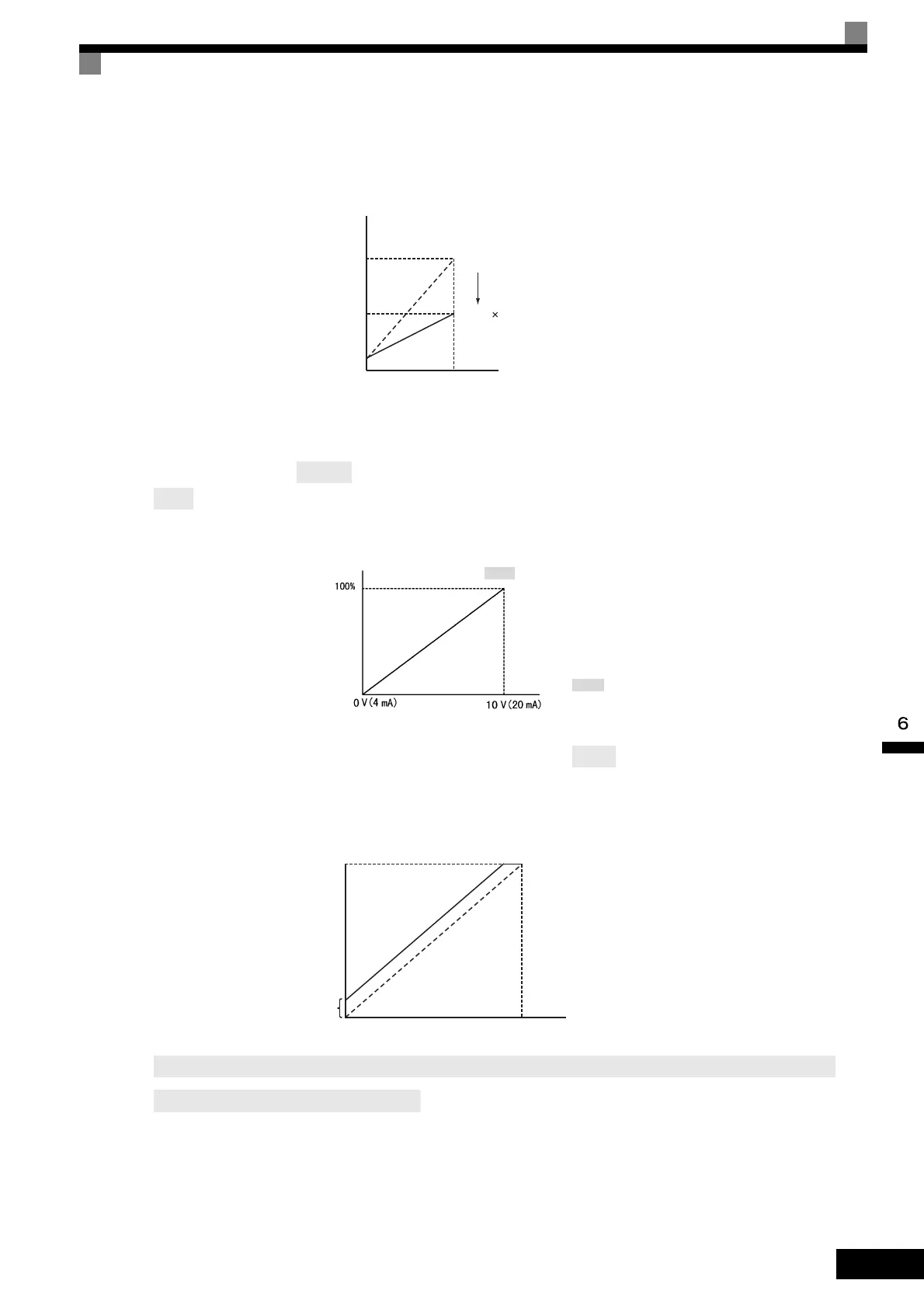
When constant H3-09 is set to 0 (add to terminal A1), the frequency equivalent to the terminal A2
input voltage is added to A1 as a bias.
Fig 6.30 Frequency Bias Adjustment (Terminal A2 or A3 Input)
For example, if H3-02 is 100%, H3-03 is 0%, and terminal A2 is set to 1 V, the frequency reference from ter-
minal A1 when 0 V is input to A1 will be 10%.
Frequency reference
H3-02
H3-02
0.5
0 10 V
Terminal A1 input voltage
100%
50%
or H3-05
or A3
Frequency bias
terminal A2 or A3 input
Multi-function analog input
terminal A2 or A3 input level
or A3
Terminal A1 input voltage
Frequency reference
H3-02
10%
Bias
0 V 10 V
When constant H3-09 or H3-05 is set to D (frequency bias 2), the frequency equivalent to the terminal A2 or
A3 input voltage is added to A1 as a bias.

 Loading...


