Individual Functions
6-101
Data Tables
The data tables are shown below. The types of data are as follows: Reference data, monitor data, and broadcast
data.
Reference Data
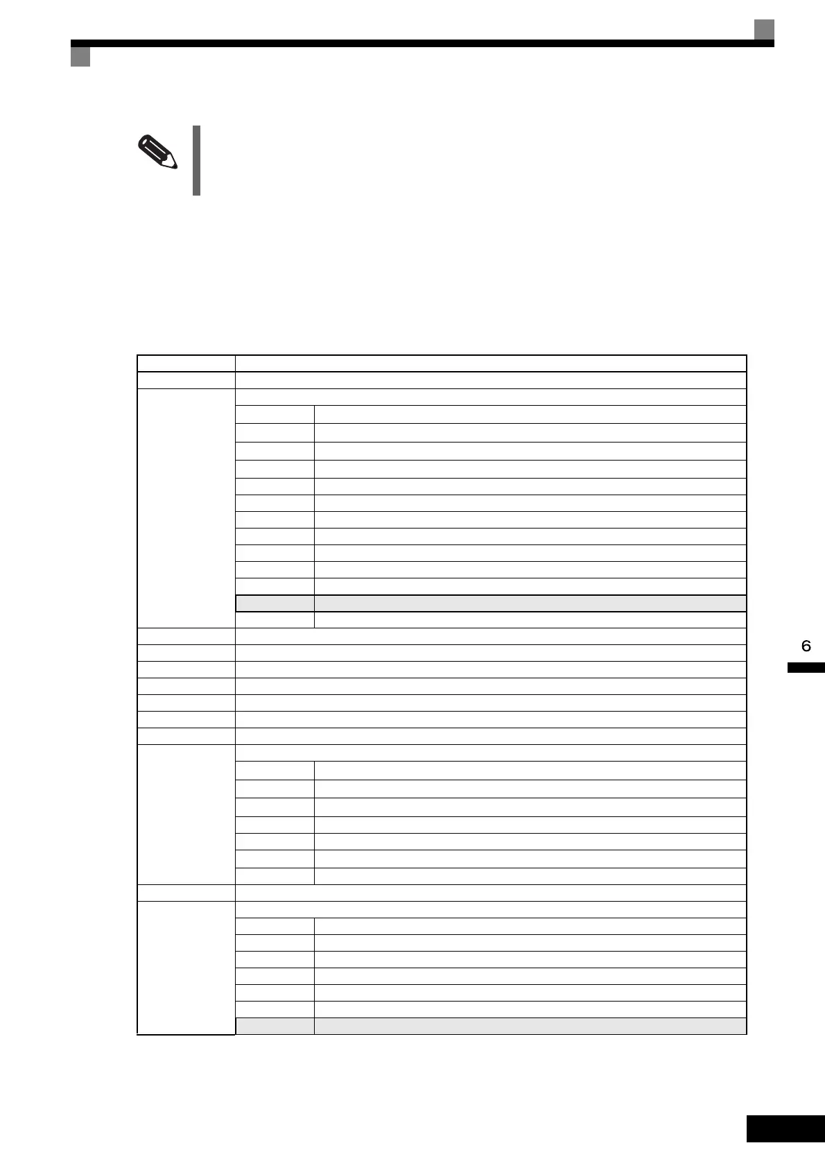
The reference data table is shown below. You can both read and write reference data.
Note Write 0 to all unused bits. Also, do not write data to reserved registers.
INFO
Set the number of data specified using command messages as quantity of specified messages x 2. Handle
response messages in the same way.
Register No. Contents
0000H Not used
0001H
Frequency reference
Bit 0
Forward Run/Stop Command 1: Forward run 0: Stop
Bit 1
Reverse Run/Stop Command 1: Reverse run 0: Stop
Bit 2
External fault 1: Error (EFO)
Bit 3
Fault reset 1: Reset command
Bit 4 ComNet
Bit 5 ComCtrl
Bit 6 Multi-function input command 3
Bit 7 Multi-function input command 4
Bit 8 Multi-function input command 5
Bit 9 Multi-function input command 6
Bit A Multi-function input command 7
Bit B Multi-function input command 8
Bit C to F Not used
0002H Frequency reference (Set units using constant o1-03)
0003H Not used
0004H Not used
0005H Not used
0006H PID target value
0007H Analog output 1 setting (-11 V/-1540 to 11 V/1540)
0008H Analog output 2 setting (-11 V/-1540 to 11 V/1540)
0009H
Multi-function contact output setting
Bit 0
Contact output (Terminal M1-M2) 1: ON 0: OFF
Bit 1
PHC1(Contact P1-PC) 1: ON 0: OFF
Bit 2
PHC2(Contact P2-PC) 1: ON 0: OFF
Bit 3 to 5 Not used
Bit 6 Set error contact (terminal MA-MC) output using bit 7. 1: ON 0: OFF
Bit 7
Error contact (terminal MA-MC) 1: ON 0: OFF
Bits 8 to F Not used
000AH to 000EH Not used
000FH
Reference selection settings
Bit 0 Not used
Bit 1 Use MEMOBUS 0006H PID target value 1: Enabled 0: Disabled
Bits 2 to B Not used
C Broadcast data terminal S5 input 1: Enabled 0: Disabled
D Broadcast data terminal S6 input 1: Enabled 0: Disabled
E Broadcast data terminal S7 input 1: Enabled 0: Disabled
F Broadcast data terminal S8 input 1: Enabled 0: Disabled

 Loading...


