2-4
IMPORTANT
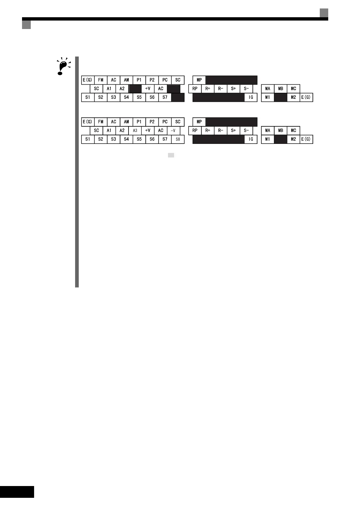
1. Control circuit terminals are arranged as shown below.
Inverters with SPEC: C or earlier
Inverters with SPEC: E or later
2. The output current capacity of the +V, terminal is 20 mA.
3. Disable the stall prevention during deceleration (set constant L3-04 to 0) when using a Braking Resistor
Unit. If this user constant is not changed to disable stall prevention, the system may not stop during decel-
eration.
4. Main circuit terminals are indicated with double circles and control circuit terminals are indicated with single
circles.
5. The wiring for a motor with a cooling fan is not required for self-cooling motors.
6. PG circuit wiring (i.e., wiring to the PG-B2 Board) is not required for control without a PG.
7. Sequence input signals S1 to S8 are labeled for sequence connections (0 V common and sinking mode)
for no-voltage contacts or NPN transistors. These are the default settings.
For PNP transistor sequence connections (+24V common and sourcing mode) or to provide a 24-V exter-
nal power supply, refer to Table 2.13.
8. The master speed frequency reference can set to input either a voltage (terminal A1) or current (terminal
A2) by changing the setting of parameter H3-13. The default setting is for a voltage reference input.
9. The multi-function analog output is a dedicated meter output for an analog frequency meter, ammeter, volt-
meter, wattmeter, etc. Do not use this output for feedback control or for any other control purpose.
10.DC reactors to improve the input power factor are built into 200 V Class Inverters for 22 to 110 kW and 400
V Class Inverters for 22 to 300 kW. A DC reactor is thus an option only for Inverters for 18.5 kW or less.
11.Set parameter L8-01 to 1 when using a breaking resistor (ERF). When using a Braking Resistor Unit, a
shutoff sequence for the power supply must be made using a thermal relay trip.
12.The permissible load of a multi-function contact output and an error contact output is 10 mA. Use a multi-
function open-collector output for a load less than 10 mA.
-V

 Loading...


