10-14
Wiring Example
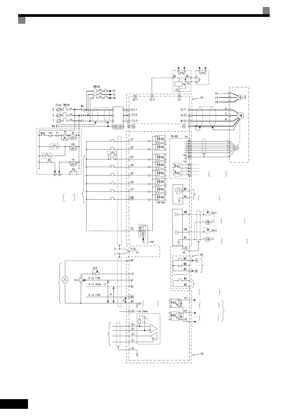
This example shows wiring for conforming to undervoltage reference.
* 1. The main circuit is separated from the terminal cover for safety reasons.
* 2. The contact output circuit is separated from the main circuit and the control circuit by reinforced insulation.
It can be connected to extra-low voltage circuits or circuits that are 250 VAC 1 A, 30 VDC 1 A or less.
* 3. The control circuit is an extra-low voltage circuit and separated from the main circuit and the contact output circuit by reinforced insulation. Always
connect it to extra-low voltage circuits.
Fig 10.6
3-phase power
2
to 24
V
50/60 Hz
Noise
filter
Braking Unit
(optional)
Thermal relay
trip contact
Level
detector
Braking Resistor Unit
(optional)
Thermal switch
contact
Inverter
CIMR-F7A2022
Cooling fan
Motor
Fault contact
for motor cooling fan
Thermal relay trip contact
for Braking Resistor Unit
Thermal relay trip contact
contact inputs
Multi-function
Factory
settings
(Main speed switching)
External
baseblock command
Forward Run/Stop
Reverse Run/Stop
External fault
Fault reset
Multi-step speed reference 1
Multi-step speed
reference 2
Jog frequency
selection
for Braking Unit
Thermal switch contact
CN5 (NPN setting)
(optional)
MEMOBUS
communications
RS-485/422
Pulse train input
Frequency
Frequency setting
adjustment
setter
External
frequency
references
Terminating
resistance
Shield wire
connection
terminal
Master speed
pulse train
Frequency setting power
Master speed reference
Multi-function anlog input
Master speed reference
4 to 20 mA (250
Ω)
[0 to 10 V (20 k
Ω
) input]
+15 V, 20 mA
0 to 10 V (20 kΩ)
0 to 10 V (20 kΩ)
Factory setting:
Not used
0 to 32 kHz (3 kΩ)
High level: 3.5 to 13.2 V input
Open collector 1
Open collector 2
Multi-function
open-collector outputs
48 VDC 50 mA max.
Default: Frequency
agree signal
Default: Zero-
speed
Error contact output
250 VAC, 10 mA min. 1 A max.
30 VDC, 10 mA min. 1 A max.
Multi-function contact output
250 VAC, 10 mA min. 1 A max.
30 VDC, 10 mA min. 1 A max.
Default: Running
signal
Multi-function analog output 1
-10 to 10 V 2 mA
Default: Output frequency
0 to +10 V
Default: Output current
0 to +10 V
-10 to 10 V 2 mA
Multi-function analog output 2
Ammeter adjustment
Ammeter adjustment
Pulse train output
Default: Output
frequency
0 to 32 kHz (2.2 kΩ)
Pulse monitor output
30 mA max.
Wiring distance:d
30 m max.
Shielded twisted-pair
wires
Pulse A
Pulse B

 Loading...


