2-26
* 1. For a 3-wire sequence, the default settings are a 3-wire sequence for S5, multi-step speed setting 1 for S6 and multi-step speed setting 2 for S7.
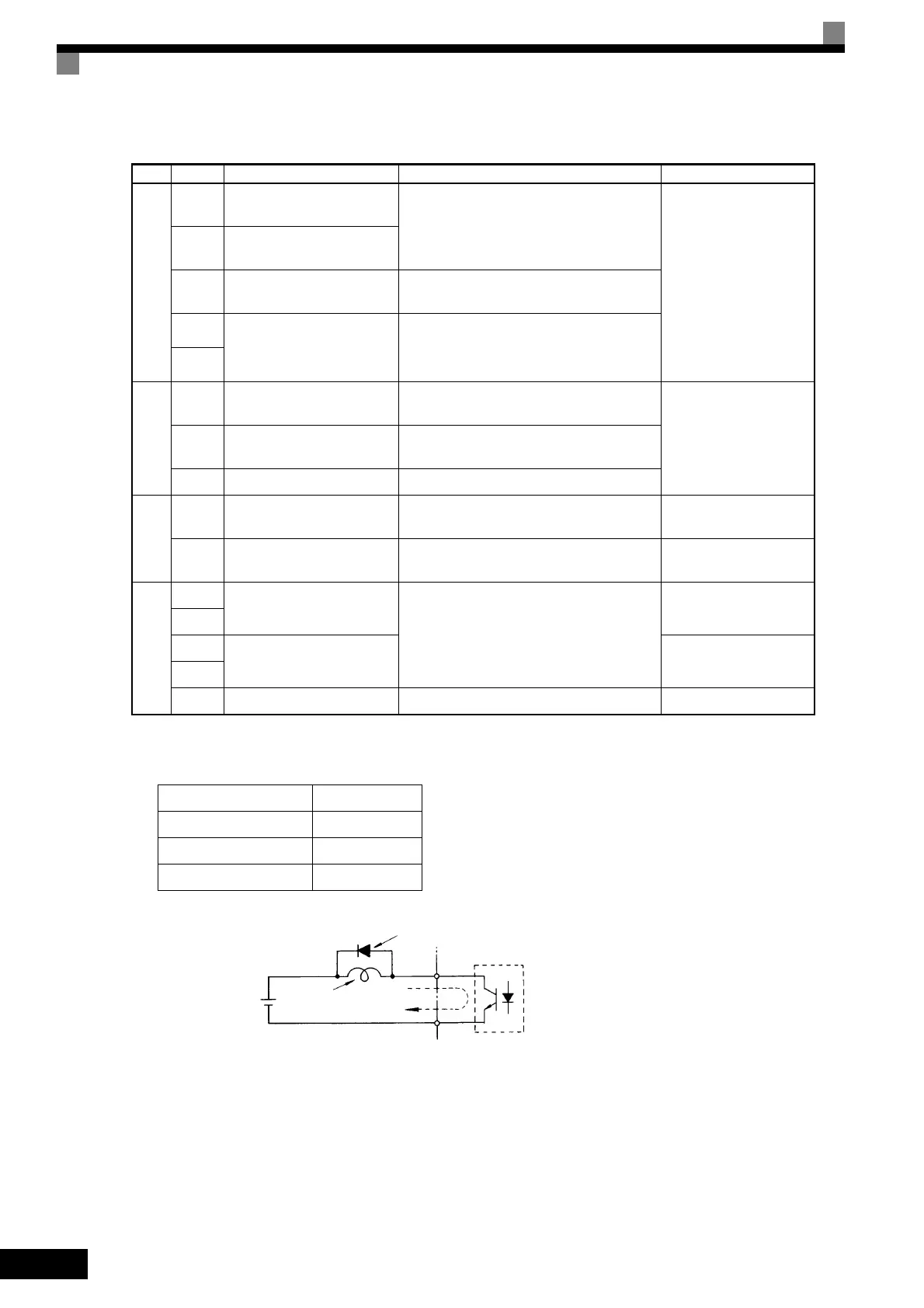
* 2. When driving a reactive load, such as a relay coil, always insert a flywheel diode as shown in Fig 2.20.
* 3. Pulse input specifications are given in the following table.
* 4. Use the photocoupler outputs when the minimum permissible load is 5 VDC or less and 10 mA or less.
Fig 2.20 Flywheel Diode Connection
Relay
outputs
MA
Fault output signal (NO con-
tact)
Fault when CLOSED across MA and MC
Fault when OPEN across MB and MC
Dry contacts
Contact capacity:
10 mA min., 1 A max. at
250 VAC
10 mA min., 1 A max. at
30 VDC
Minimum permissible
load: 5 VDC, 10 mA
*4
MB
Fault output signal (NC con-
tact)
MC
Relay contact output com-
mon
-
M1
Multi-function contact output
(NO contact)
Factory setting: Operating
Operating when CLOSED across M1 and
M2.M2
Analog
moni-
tor out-
puts
FM
Multi-function analog moni-
tor 1
Factory setting: Output frequency
0 to 10 V/100% frequency
-10 to +10 VDC ±5%
2 mA max.AM
Multi-function analog moni-
tor 2
Factory setting: Current monitor
5 V/Inverter's rated current
AC Analog common -
Pulse
I/O
RP
Multi-function pulse input
*3
Factory setting: Frequency reference input
(H6-01 = 0)
0 to 32 kHz (3 kΩ)
MP Multi-function pulse monitor
Factory setting: Output frequency
(H6-06 = 2)
0 to 32 kHz (2.2 kΩ)
RS-
485/
422
R+
MEMOBUS communica-
tions input
For 2-wire RS-485, short R+ and S+ as well
as R- and S-.
Differential input, photo-
coupler isolation
R-
S+
MEMOBUS communica-
tions output
Differential output, pho-
tocoupler isolation
S-
IG Communications shield wire - -
Low level voltage 0.0 to 0.8 V
High level voltage 3.5 to 13.2 V
H duty 30% to 70%
Pulse frequency 0 to 32 kHz
Table 2.11 Control Circuit Terminals (Continued)
Type
No. Signal Name Function Signal Level
External power:
48 V max.
Coil
Flywheel diode
50 mA max.
The rating of the flywheel diode
must be at least as high as the
circuit voltage.

 Loading...


