APPENDIX 2 LIST OF PARAMETER NUMBERS (Co~fd)
,6,15;~“r
‘~ ~“~
I).
_ ... .— .—
-L—.. ,
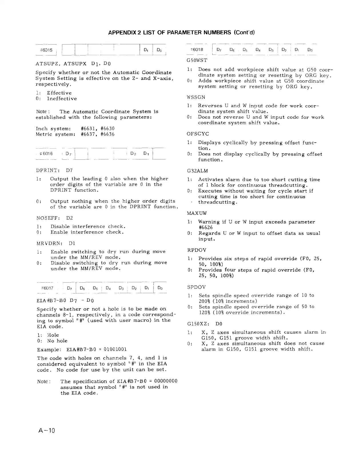
AT SUPZ, ATSUPX Dl, DO
Specify whether or not the Automatic Coordinate
System Setting is effective on the Z- and X-axis,
respectively.
].:
Effective
0: Ineffective
Note :
The Automatic Coordinate System is
established with the following parameters:
Inch system:
#6631, #6630
Metric system: #6637, #6636
.——— ——
Z 6016
I
D711
,—. .— -——.
DPR.lNT: D7
1: Output the leading
order digits of the
DPRINT function.
~—
D2
D, I
L—.
O also when the higher
variable are O in the
0:
Output nothing when the higher order digits
of the variable are ‘0in the DPRINT function .
NO SEFF: D2
1:
Disable interference check.
o:
Enable interference check,
MR’VDRN: D1
1:
Enable switching to dry run during move
under the MM/REV mode.
o:
Disable switching to dry run during move
under the MM IREV mode.
~—-
=6017 D71DGDS’DAD3D2
D, ~ Do
——.
—_L . .
EIA~#B7-BO D7 - D()
Specify whether or not a hole is to be made on
channels 8-1, respectively, in a code correspond-
ing
to symbol “#“ (used with user macro) in the
EIA code.
1:
Hole
o: N o hole
Example:
EIA#B7-Bo ‘ 01001001
The code with holes on channels 7, 4, and 1 is
considered equivalent to symbol “#’iin the EIA
code .
No code for use by the unit can be set.
Note : The specification of EIA#B7-BO = 00000000
assumes that symbol “#“ is not used in
the EIA code.
——
~
.— — –——..—
:6018
jD7D6D5DdD3 D2, DID0
,. __ __
G50WST
1:
Does not add workpiece shift value at G50 coor-
dinate system setting or resetting by ORG key.
o: Adds workpiece shift value at G50 coordinate
system setting or resetting by ORG key.
WSSGN
1: Reverses U and W input code for work coor-
dinate system shift value.
o: Does not reverse U and W input code for work
coordinate system s“hiftvalue.
OFSCYC
1: Displays cyclicallyby pressing offset func-
tion.
o:
Does not display cyclicallyby pressing offset
function.
G32ALM
1: Activates alarm due to too short cutting time
of 1 block for continuous ihreadcutting.
o:
Executes without waiting for cycle start if
cutting time is too short for continuous
threadcutiing.
MAX UW
1:
Warning if U or w input exceeds parameter
#6626
o: Regards U or W input to offset data as usual
input.
RPDOV
1:
Provides six steps of rapid over~ide (FO, 25,
50, 100%)
o:
Provides four steps of rapid override (FO,
25, 50, 100%)
SPDOV
1:
Sets spindle speed override range of 10 to
200% (10% increments)
o:
Sets spindle speed override range of 50 to
120% (10% override increments) .
G150XZ: DO
L: X, Z axes simultaneous shift causes alarm in
G150, G151 groove width shift.
o:
X, Z axes simultaneous shift does not cause
alarm in G150, G151 groove width shift.
A--1O

 Loading...


