Preparing for Measurement
3-31
IM AQ6370E-02EN
3
Connecting Optical Fibers
5.
Open the instrument’s optical input connector cover.
6.
Connect the optical fiber’s optical connector to the optical input connector on the instrument.
Setting the optical fiber connector
7.
Press SETUP. The setup menu is displayed.
8.
Tap More to display the More 2/2 menu.
9.
Tap Fiber Connector. Each time you tap, toggles between Norm and Angled. Set Angled if
the optical fiber under test is APC (angle lap PC). Otherwise, set Normal.
Note
• If you set Fiber Connector to Angled, is displayed in the measurement conditions area.
• The instrument’s measurement accuracy specification is for when Fiber Connector is set to Norm.
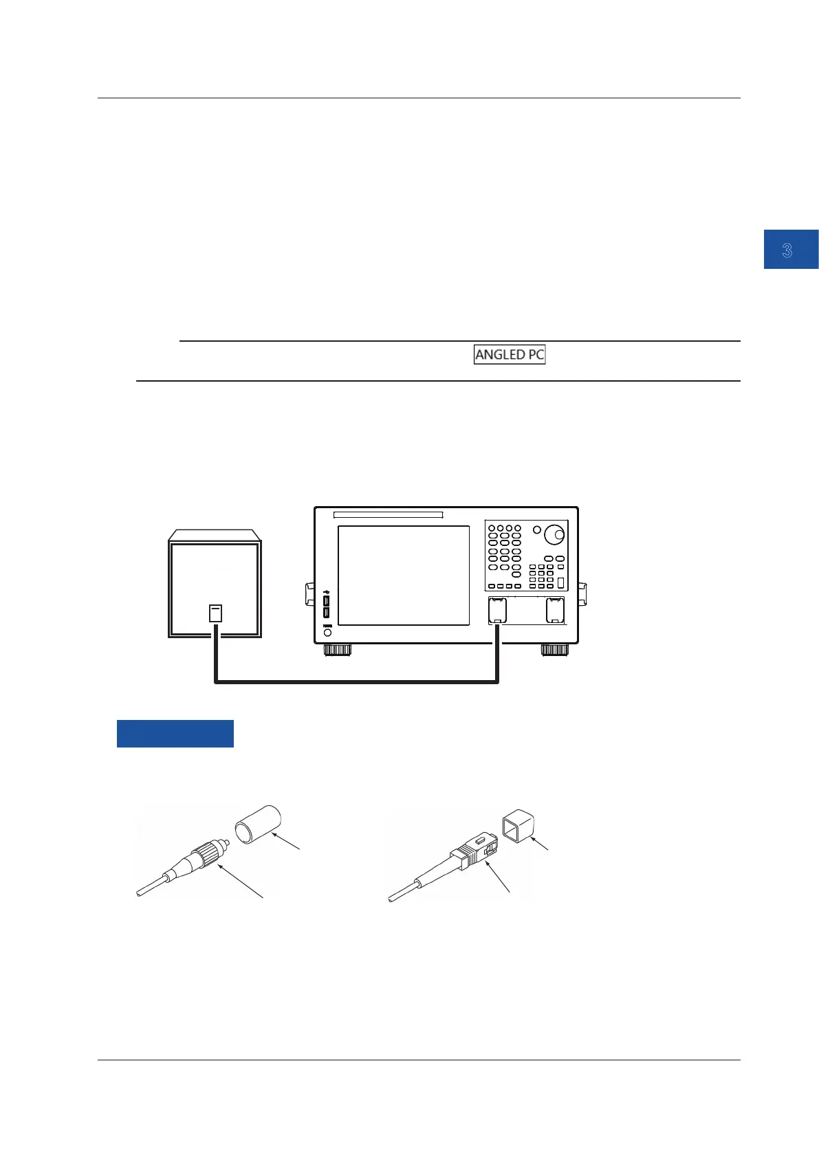
Connecting the DUT (Light Source)
7.
Clean the top of the optical connector on the other end of the optical fiber with a fiber cleaner.
8.
Connect the optical connector on the other end of the optical fiber to the optical connector on
the DUT.
Light source
9.5/125 μm Single mode MIR optical fiber
AQ6370E
Explanation
Optical Connectors Types
The instrument can use FC, or SC type optical connectors.
FC type optical connector
Cap
SC type optical connector
Cap
3.8 Connecting the DUT

 Loading...

