<4. Wiring>
37
IM 01E24A01-01EN
Protective
grounding
terminals
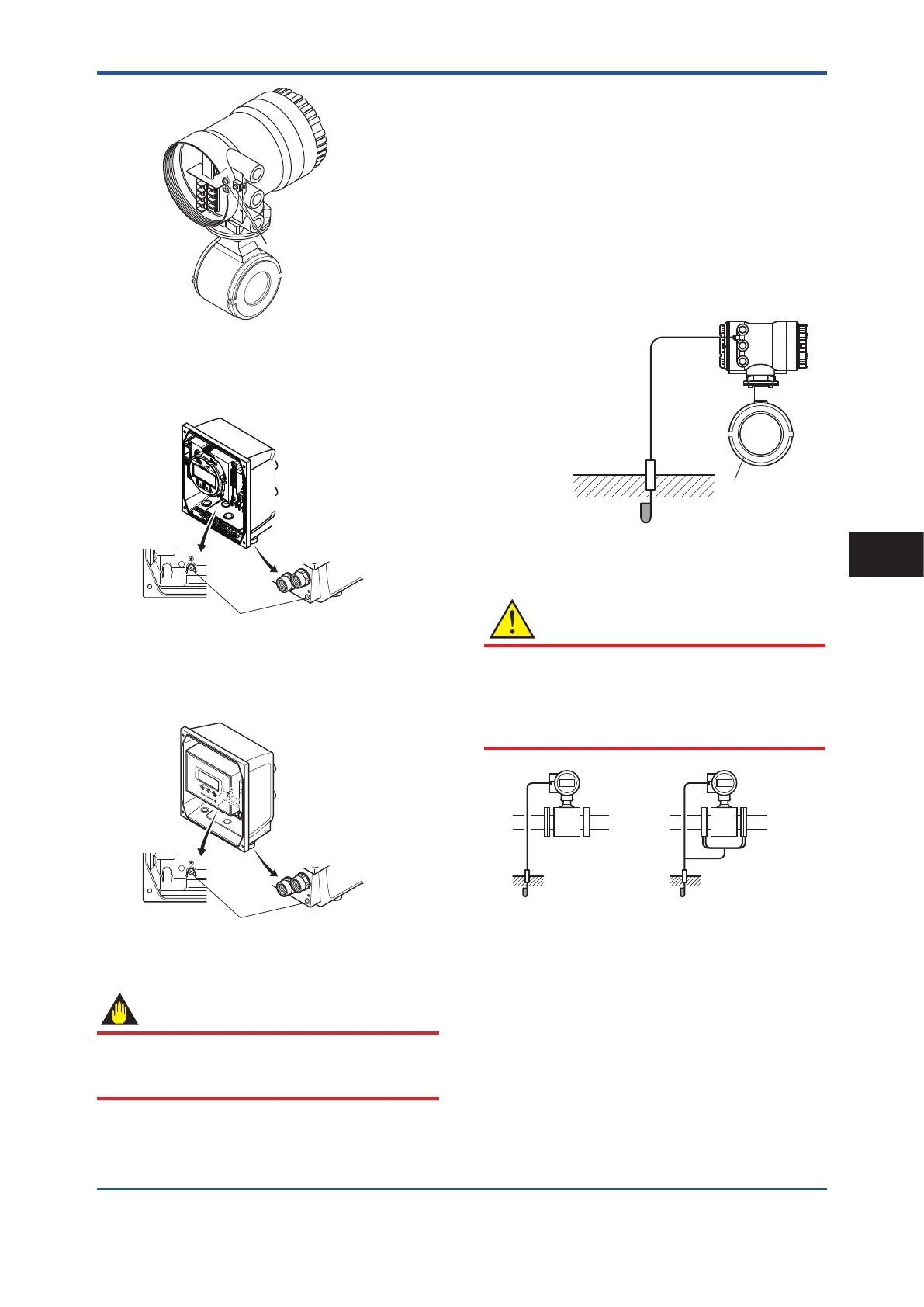
Figure 4.4.4 Position of Protective Grounding Terminal
(Integral Type and AXW4A Remote
Transmitter)
Protective grounding terminals
Figure 4.4.5 Position of Protective Grounding Terminal
(AXG1A Remote Transmitter)
Protective grounding terminals
Figure 4.4.6 Position of Protective Grounding Terminal
(AXFA11 Remote Transmitter)
IMPORTANT
Improper grounding may result in an adverse effect
on the ow measurement. Ensure that the product is
properly grounded.
The electromotive force of the magnetic owmeter
is minute and it is easily affected by noise, and the
reference electric potential is the same as that of the
measuring uid. Therefore, the reference electric
potential (terminal potential) of the sensor and transmitter
also need to be the same as that of the measuring uid.
Moreover, the potential must be the same as the ground.
The magnetic owmeter is equipped with an grounding
ring that makes a connection with the charge of the
measured uid for grounding and protects the lining.
Grounding rings are supplied with the products when
specied with dedicated optional code.
Grounding Resistance: 10 Ω or less (Class C requirements)
Note:
When lightning protection performance by the built-in lightning
protectors is not required, grounding resistance 100 Ω or less
(Class D requirements) can be applied.
F0429.ai
600 V vinyl-insulated cable
grounding ring
Cable cross section area:
2 mm
2
, and cross section
area larger than power cable
CAUTION
•
The grounding should satisfy grounding resistance
requirement, 100 Ω or less (Class D grounding).
•
For explosion protection type, the grounding must
satisfy the domestic electrical requirements as
regulated in each country.
F0430.ai
In case grounding rings
are used.
In case grounding rings are not used.
(Available only for metal piping)
Figure 4.4.7 Grounding (Integral Flowmeter)
Wiring
4
 Loading...
