<4. Wiring>
38
IM 01E24A01-01EN
4.4.4 Connecting to External Products
WARNING
• Before wiring with external products, be sure to turn
off the power supply of the magnetic owmeter.
• Be sure the power supply of the external products is
turned off, and then start wiring.
Read Section 4.6 for connection to external products.
4.4.5 Wiring Procedures
(1) For Integral Flowmeter and AXW4A Remote
Transmitter
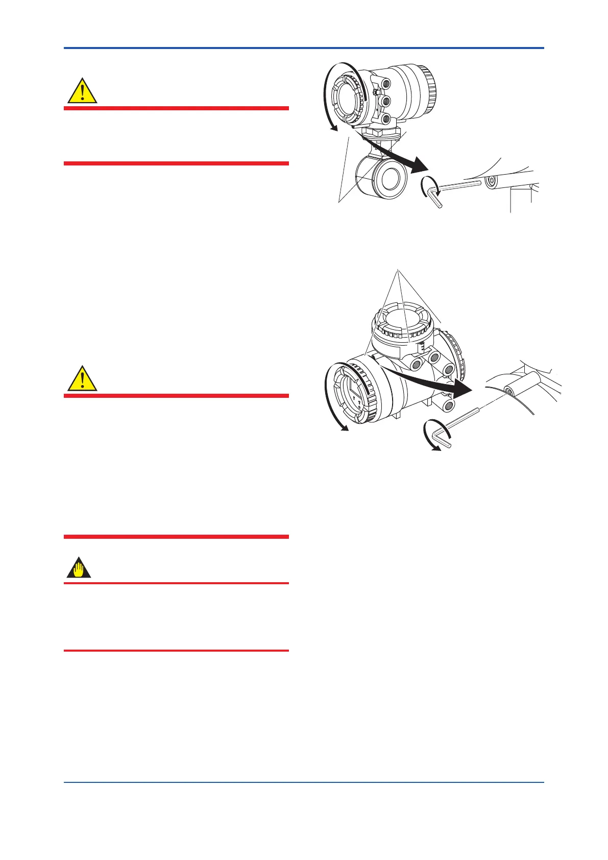
1) Removing the Cover
Loosen the cover locking screw (1 and 3) (See
Figure 4.4.7 and Figure 4.4.8) clockwise using a
hexagonal wrench (nominal size 3) to unlock the
cover. Upon shipment from the manufacturing
plant, the cover is unlocked. Hold the owmeter
with your hand and remove the cover by turning it
in the direction of the arrow as shown below.
WARNING
•
When opening and closing the cover, be sure to
handle the cover carefully so that there are no damage
and foreign matter adhesion at its threads and O-ring.
Keep checking their condition and clean the threads in
case of adhering the foreign matter.
•
Replace the cover in case the treads receive
damages.
•
Replace the O-ring if there is any scarring or
transformation. And apply silicone based grease at
the O-ring in case of the shortage and exhaustion of
grease.
IMPORTANT
•
When closing the cover, close it with both hands until
the cover does not turn in order to bring the housing
and cover into tight contact.
•
Tighten while conrming that the cover rotates
smoothly.
F0431.ai
Cover locking screws
(1)
(2)
Figure 4.4.8 Removing the Terminal Box Cover for Integral
Flowmeter
F0432.ai
(2)
(3)
Cover locking screws
(1)
Figure 4.4.9 Removing the Terminal Box Cover for AXW4A
Remote Transmitter
2) Terminal Conguration
When the cover is removed, the connection
terminals will be visible.
The description of the terminal symbols is shown
in Figure 4.4.9 or Figure 4.4.10.
3) Wiring Procedure
1. Check the product’s power is off.
2. Wire the signal cable and excitation cable to
each terminal.
3. Install the terminal cover.
4) Installing the Cover
Install the cover to the owmeter by turning
it clockwise. Tighten the cover locking screw
(1 and 3) (See Figure 4.4.7 and Figure 4.4.8)
counterclockwise using a hexagonal wrench
(nominal size 3) to lock the cover.
 Loading...
