<4. Wiring>
41
IM 01E24A01-01EN
3) Installing the Cover
While supporting the front of the cover with your
hand, ip the connecting screw protective cover
over, and tighten the four connecting screws.
(4) For AXFA11 Remote Transmitter
1) Removing the Cover
While supporting the front of the cover with your
hand, ip the connecting screw protective cover
over, and remove the four connecting screws.
F0438.ai
Figure 4.4.14 Removing the Front Cover
(AXFA11 Remote Transmitter)
2) Terminal Conguration
When the cover is removed, the connection
terminals will be visible as shown below.
F0439.ai
N/– L/+ EX2EX1 P–P+
I+ I– AL+ AL– C SA A B SB
SI1+ SI2+ COM
SO1+ COMSO2+
F0440.ai
I+ I–
CURRENT OUT
AL+ AL– C SA A B SB
ALARM OUT
N/– L/+
POWER SUPPLY
EX2EX1
EXCITATION
P–P+
PULSE OUT
SIGNAL
SI1+ SI2+ COM
STATUS IN
SO1+ COMSO2+
STATUS OUT
Figure 4.4.15 Terminal Conguration
(AXFA11 Remote Transmitter)
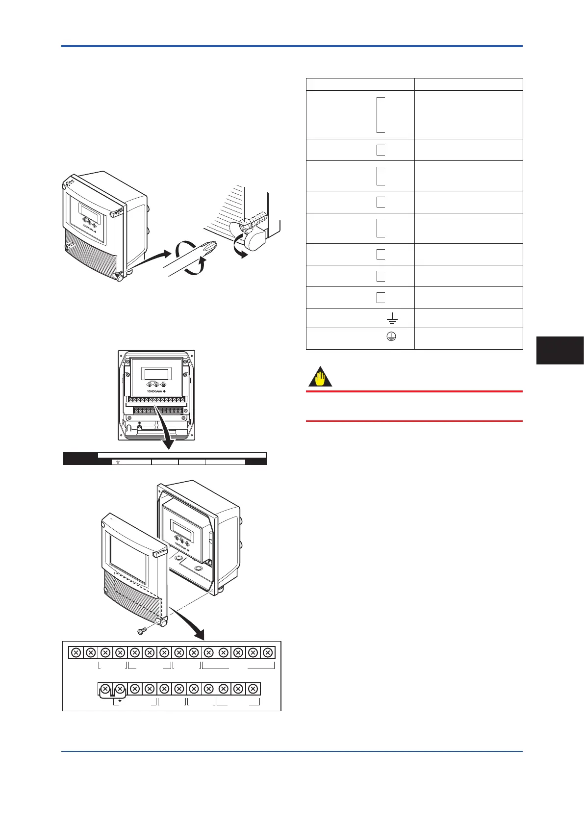
Table 4.4.2 Terminal Symbols
(AXFA11 Remote Transmitter)
Terminal Symbol Description
SIGNAL
C
SA
A
B
SB
Flow signal input
ALARM OUT
AL+
AL-
Alarm output
STATUS OUT
SO1+
SO2+
COM
Status output (Two outputs)
CURRENT OUT
I+
I-
Current output
4−20 mA DC
STATUS IN
Sl1+
Sl2+
COM
Status input (Two inputs)
PULSE OUT
P+
P-
Pulse output
EXCITATION
EX1
EX2
Excitation current output
POWER SUPPLY
L /+
N/-
Power supply
Functional grounding
Protective grounding (Outside of
the terminal)
IMPORTANT
Do not wire the terminal without terminal symbols in
terminal layout labels.
3) Installing the Cover
While supporting the front of the cover with your
hand, ip the connecting screw protective cover
over, and tighten the four connecting screws.
Wiring
4
 Loading...
