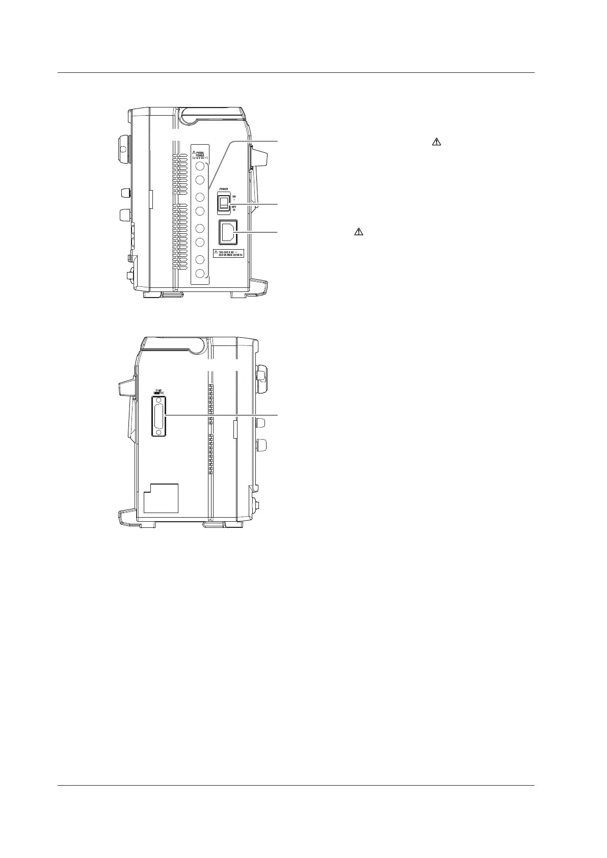
EasyManuals Logo

YOKOGAWA DLM4038 Getting Started Guide

YOKOGAWA DLM4038
109 pages
To Next Page IconTo Next Page
To Previous Page IconTo Previous Page
Page #19 background imageLoading...
Page #19 background image
1-2
IM DLM4038-03EN
Right Side Panel
Power connector → Section 2.3
Main power switch → Section 2.3
8 probe power terminals (optional)
Use these terminals to supply power to a YOKOGAWA
FET probe or current probe. → Section 2.4
Inlet holes
Left Side Panel
GP-IB connector
Use this connector to communicate with the DLM4000
through the GP-IB interface.
→ Communication Interface User’s Manual
Inlet holes
1.1 Top Panel, Front Panel, Right Side Panel, Left Side Panel, and Rear Panel

Table of Contents

Other manuals for YOKOGAWA DLM4038

Questions and Answers:

Question and Answer IconNeed help?

Do you have a question about the YOKOGAWA DLM4038 and is the answer not in the manual?

YOKOGAWA DLM4038 Specifications

General IconGeneral
BrandYOKOGAWA
ModelDLM4038
CategoryTest Equipment
LanguageEnglish

Related product manuals