2. Transportation, Storage and Installation
2-45
TI 32P01J10-01EN
Mar. 29, 2019-00
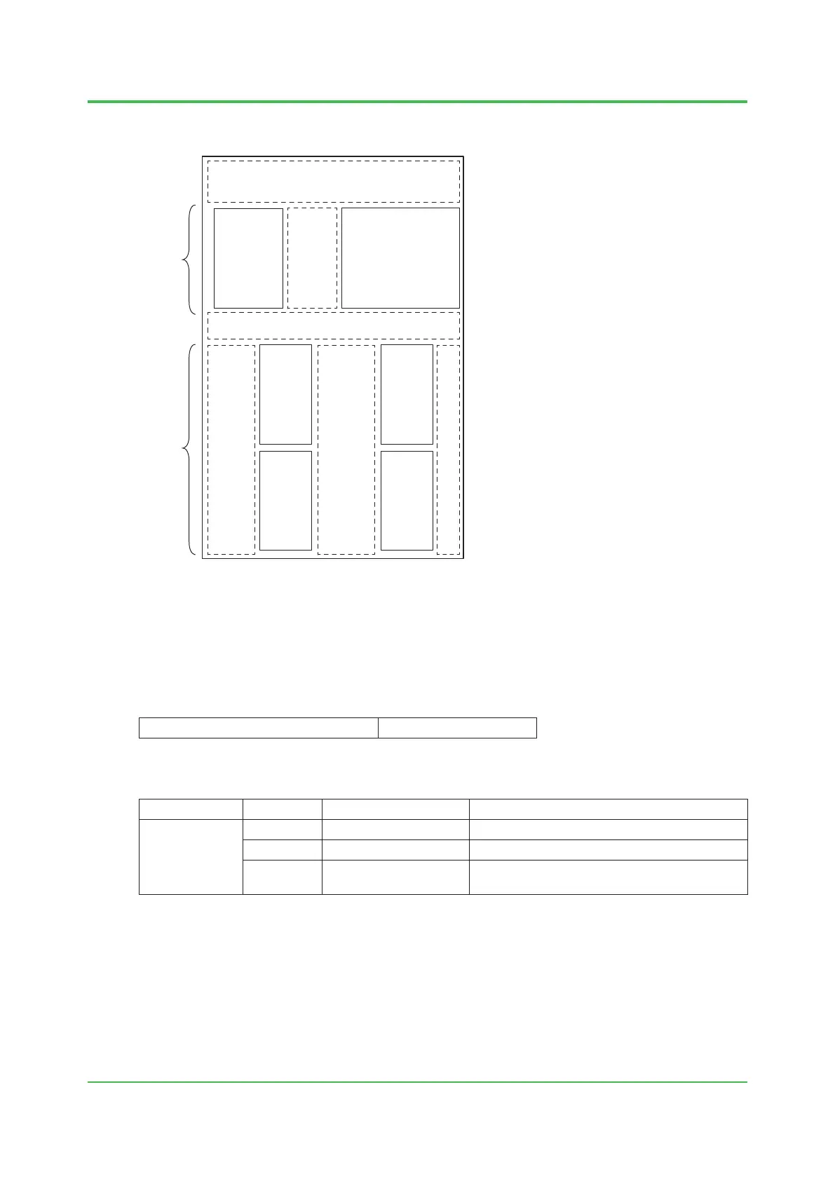
The following shows how to mount N-IO nodes (Non-Intrinsic Safety barrier) in a junction box:
F020531.ai
Junction Box
Non-mounting area (1unit or more)
NIU
NIU
IOBP
Heat-generating
device mounting area
(max. 40 W)
IOBP IOBP
IOBPIOBP
Non-mounting area (2 units) / Wiring is possible
Non-mounting area
/ Wiring is possible
(30 mm)
Heat-generating device non-mounting
area / Wiring is possible
Wiring area
Wiring area
Figure Example of Mounting N-IO Nodes (Non-Intrinsic Safety Barrier) in a Junction Box
Example of Mounting N-IO Nodes (Intrinsic Safety Barrier) in a Junction Box
Temperature conditions
In this example, the ambient temperature is assumed to be the following.
Junction Box ambient temperature 50 °C or less
Maximum numbers of units that can be mounted
Type Model Number of units that can be mounted per side
Per junction box
NIU S2NN30D Up to 1
IOBP_IS S2BN4D or S2BN5D Up to 2 (2 rows × 1 shelf)
Other
Heat-generating device
(*1)
heat generation: 20 W or less
*1: The device to be mounted shall be selected from those that have the ambient temperature range of +15 °C or more.
Heat-generating devices other than the above shall not be mounted in the junction box.
In this example, IOBP cannot be mounted.
 Loading...