2. Transportation, Storage and Installation
2-46
TI 32P01J10-01EN
Mar. 29, 2019-00
Mounting conditions
• Do not mount the IOBP_IS so that its heat-generating part (Barrier or I/O) is located
immediately under the N-ESB Bus module (S2EN501). The IOBP_IS may be mounted
immediately under the power supply of the NIU (S2PW50x).
• The NIU shall be mounted with a 2-unit or more space from the ceiling of the junction box.
• A 2-unit or more space shall be provided between the NIU and IOBP_IS.
• To mount heat-generating devices other than NIU and IOBP_IS shall be mounted with 30-
mm intervals on the right of the NIU on the top shelf. The specications of the devices shall
be observed.
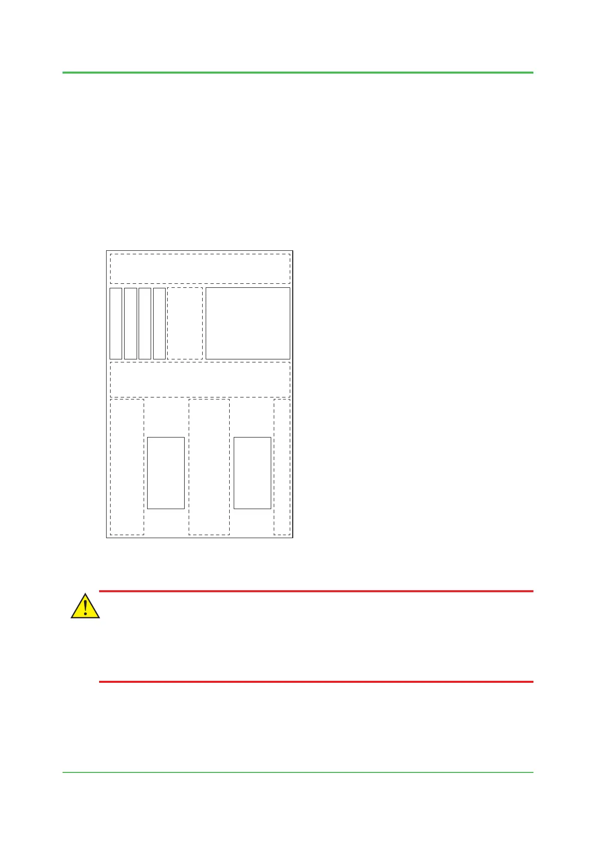
The following shows how to mount N-IO nodes (Intrinsic Safety barrier) in a junction box:
F020532.ai
Junction Box
Non-mounting area (2unit or more)/Wiring is possible
NIU
Heat-generating
device mounting area
(max. 20 W)
IOBP_IS IOBP_IS
Non-mounting area (2 units or more) /
Wiring is possible
Non-mounting area
/ Wiring is possible
(30 mm or more)
Heat-generating device non-mounting
area (under the N-ESB Bus module)
Wiring is possible
Field wiring area
Wiring area
NIU
Power supply unit
Power supply unit
Figure Example of Mounting N-IO Nodes (Intrinsic Safety Barrier) in a Junction Box
CAUTION
The wiring that will be intrinsic safety circuits must be installed so that they are electrically
separated from the wiring of non-intrinsic safety circuits, including the in-cabinet wiring. Install the
wiring according to the IEC 60079-14 standards or the requirements for explosion-proof wiring of
the country where the system is used.
 Loading...