3. Cabling
3-40
TI 32P01J10-01EN
Connecting Signal Cables to Terminals (for N-IO)
Connecting cables to pressure clamp terminals (S2BN1D-1)
Follow these steps to connect cables to pressure clamp terminals:
1. Open the cover of the terminal block of the base plate for N-IO I/O.
2. Conrming the cable polarity, insert the cable to the pressure clamp terminal. Tighten the
screw using the special tool (a screwdriver conforming to the DIN 5264B standard a tip
width of 0.6 mm and a shaft diameter of 3.5 mm) with a fastening torque of 0.5 N·m.
3. Pull the cable gently to check that it is xed securely.
4. Close the cover of the terminal block of the base plate for N-IO I/O.
Connecting cables to spring clamp terminals (S2BN1D-2)
Follow these steps to connect cables to spring clamp terminals:
1. Open the cover of the terminal block of the base plate for N-IO I/O.
2. Pressingly expand the spring clamp terminal with a at-blade screwdriver.
3. Insert a cable without pulling out the screwdriver.
4. Pull out the at-blade screwdriver.
5. Pull the cable gently to check that it is xed securely.
6. Close the cover of the terminal block of the base plate for N-IO I/O.
N-IO Signal Cabling
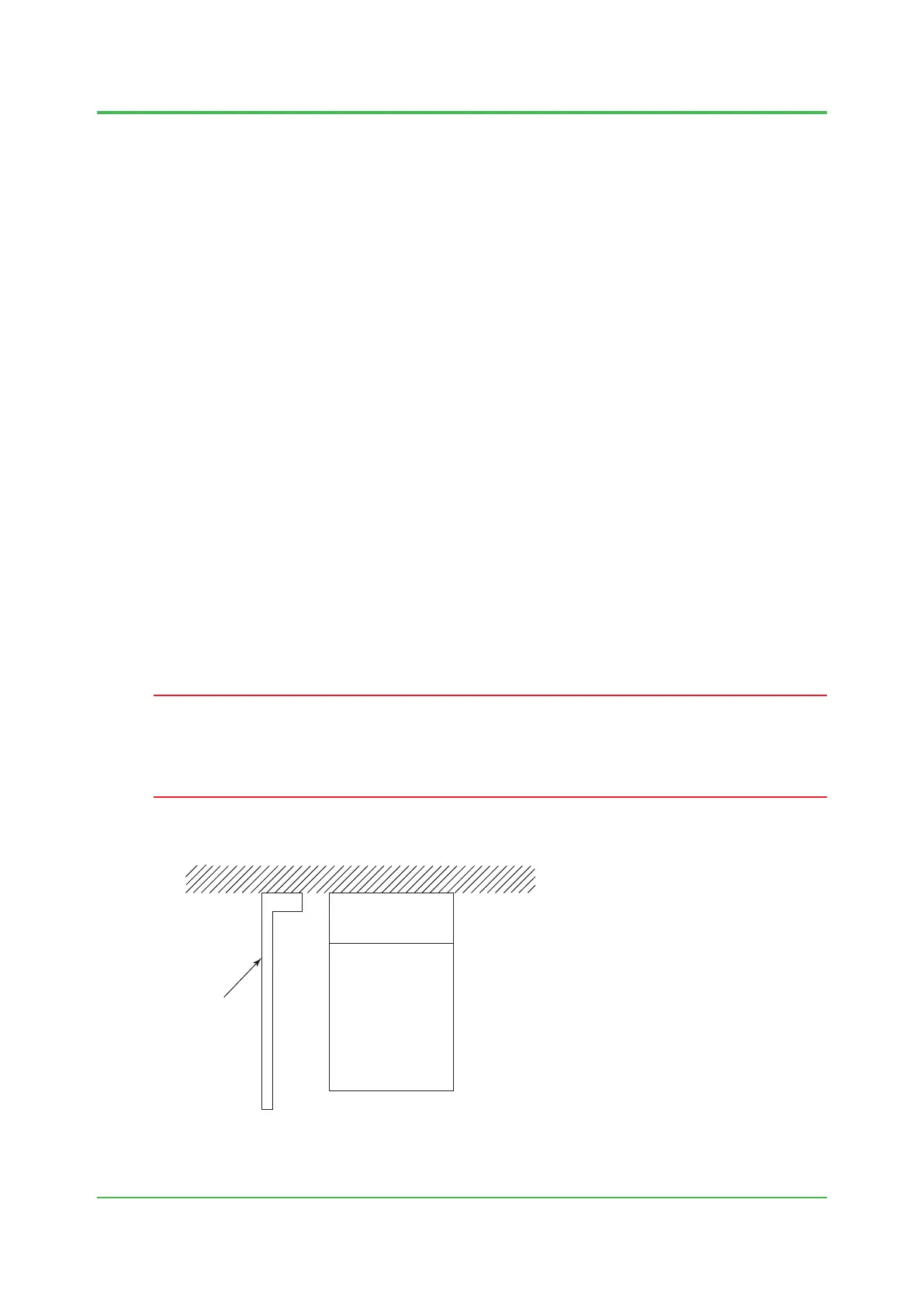
IMPORTANT
The signal cable for the top IOBP must be wired at the innermost part in the eld control area as
the gure shows.
When xing cables to a clamp, allow enough space so that the cards can be maintained.
Push in the signal cables for the top IOBP as far as they will go.
F030509.ai
Front
IOBP
(1)
(2)
(3)
(4)
(5)
(1): Signal Cables for
the top IOBP
(5): Signal Cables for
the Bottom IOBP
Cable binding
bar
(6)
Figure Cabling
Oct. 5, 2018-00
 Loading...